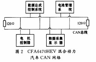
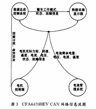
introduction This article refers to the address: http:// Hybrid vehicles (HEVs) indicate that there are multiple types of power involved in the car drive, generally referred to as the fuel engine and the motor. At present, the research and development of hybrid vehicles at home and abroad is in the ascendant. This type of vehicle combines the advantages of traditional automobile engine drive and motor drive. The main energy source is still gasoline and diesel. The hybrid vehicle not only fully utilizes the advantages of long working time and good power of the fuel engine, but also has the advantages of no pollution and low noise of the motor, and has the characteristics of low fuel consumption and low pollution. Moreover, the hybrid car can maintain the balance of power during operation, unlike pure electric vehicles, which need to be equipped with special chargers and other supporting equipment. In the near future, hybrid vehicles will form a three-legged situation with traditional fuel vehicles and pure electric vehicles. Hybrid vehicles have added motors, batteries and other components to the traditional fuel vehicles. This requires motor controllers, battery management systems, and energytrain control systems to coordinate the engine and motor to make each device work efficiently. District, improve energy utilization, and optimize vehicle performance. The brake controller, transmission controller, engine ECU (Engine Control Unit) and other electronic control equipment and instrument instruments in the traditional fuel vehicle use CAN bus for communication. The CAN bus has strong real-time performance, long transmission distance and strong anti-electromagnetic interference capability. Low cost, multi-master station, etc. Hybrid vehicles follow the tradition of fuel vehicles. The new motor controller, battery management system and energy supply control system are also integrated into the CAN bus for information exchange. 2 CAN bus technology introduction CAN (Controller Area Network) is an advanced serial communication protocol. It was originally developed as a serial data communication bus for solving the data exchange between many control and test instruments in automobiles. It belongs to the field bus field. In 1993, CAN bus became an international standard (ISO11898: High-speed control LAN digital information exchange standard for road vehicles), which effectively supports distributed control and real-time control, and uses the priority CSMA/CD protocol to arbitrate the bus. Therefore, the CAN bus allows multiple stations to transmit at the same time, thus ensuring the real-time information processing, and making the CAN bus network can constitute a multi-master structure system, ensuring the reliability of the system. In addition, CAN adopts short frame structure, and each frame of information has checksum and other error detection measures to ensure real-time data and low transmission error rate. The transmission medium can use twisted pair, coaxial cable or fiber. 3 Hybrid car CAN bus network The following is an example of the Changfeng CFA6470HEV hybrid car. CFA6470HEV takes the CFA6470G four-wheel drive off-road vehicle as the platform and removes the transfer case. The engine only drives the rear axle. The motor drives the front axle with Ni-MH power battery as energy. The front and rear wheels achieve the same speed through the ground friction. The energytrain control system coordinates the start and stop of the engine and the output of the motor according to the state of the vehicle. The functional structure of the entire CFA6470HEV is shown in Figure 1. For the CFA6470HEV hybrid car, we have built a CFA6470HEV hybrid car CAN control network as shown in Figure 2. The energytrain control system and motor controller are based on TMS320LF240x (see TI: TMS320LF24xADSPControllers Reference Guide, 1999). The digital signal processor is CPU, and the battery management system and data acquisition display are 89C52. The data flow diagram between its nodes is shown in Figure 3. 4 CAN interface design of hybrid vehicle energy assembly control system Hybrid vehicle energytrain control system, as the central processor of hybrid vehicle, requires high real-time performance, strong computing power, and is connected to the CAN bus. Therefore, its CPU uses TI's TMS320LF2407A embedded CAN controller. 4.1 Introduction to TMS320LF2407ACAN Controller The CAN controller module of TMS320LF2407A is a complete CAN controller. It is a 16-bit peripheral module, fully supports CAN2.0B protocol, supports data frames, remote frames, and can work in standard mode or extended mode. It uses mailbox to send and receive data, configurable receiving mask word for receiving mailbox, programmable bit timer, programmable interrupt configuration, programmable CAN bus wake-up function, automatic reply to remote request, when data is lost or data is lost during arbitration The CAN controller automatically retransmits with bus error diagnostics and can work in self-test mode. The CAN controller of TMS320LF2407A uses the mailbox mechanism to send and receive data, which is different from the general CAN controller. A typical CAN controller (such as SJA1000) has only one transmit data area, one receive buffer, and a 64-byte receive buffer. When sending different identifier data frames, the identifier register must be changed. When receiving different identifier data frames, the mask registers must be open to data frames of different identifiers. The TMS320LF2407A CAN controller has 6 mailboxes, 2 of which receive mailboxes (MBOX0, 1), 2 send mailboxes (MBOX4, 5), and 2 can be configured to receive or send mailboxes (MBOX2, 3), each sent The mailbox is equivalent to a transmission data area, and each receiving mailbox is equivalent to a receiving data area, so that the TMS320LF2407A can receive at least 2 frames (up to 4 frames) of data frames of different identifiers without changing the identifier register or receiving the mask register. At least 2 frames (up to 4 frames) of data frames with different identifiers can be sent, but not at the same time. This is suitable for CAN nodes that send and receive data frame types are not many. The CAN controller of the TMS320LF2407A has 15 16-bit control registers that control the CAN bit timer, mailbox transmit or receive enable, error status, and CAN interrupt. See Reference 1 for details. 4.2 CAN interface hardware design The CAN interface hardware circuit is shown in Figure 4. The CAN control module of the TMS320LF2407A is connected to the CAN transceiver PCA82C250 through a high-speed opto-isolation module (two high-speed opto-isolators 6N137). The CAN interface software is divided into three parts: an initialization program, a data transmission program, and an interrupt reception program. The data interpretation function is completed by the main program. 4.3.1 Initializing the CAN Controller According to the requirements of the whole vehicle, the hybrid vehicle energytrain control system needs to receive data frames of four different identifiers and send data frames of two different identifiers. Therefore, we configure the MBOX2 and 3 of the TMS320LF2407A to receive mode. Configure the identifier and receive the mask word once in the program. Therefore, the initialization program completes the baud rate, the mailbox identifier, the receiving mask word, the transmission interrupt is not enabled, and the receiving interrupt is enabled. The initialization process is shown in FIG. 5. Since the mailbox identifier has been allocated in the initialization program at one time, the sending program only writes the data to be sent into the data area of ​​the corresponding mailbox, and sets the sending request bit to start sending. After the transmission is completed, the sending acknowledge bit can be reset. The data transmission process is shown in Figure 6. The interrupt receiving service program sets the corresponding data reception flag and resets the reception suspension bit and the reception interrupt flag bit. The main program reads data and interprets the data according to the data reception flag. This reduces the amount of time that the interrupt service routine takes up CPU. 5 TMS320LF2407ACAN interface circuit design key issues In order to further suppress interference, optical isolation circuits are often used in CAN bus interfaces. The opto-isolator is typically located between the CAN controller and the transceiver. A high-speed optical isolation 6N137 optical isolator is used in the CAN bus interface of the hybrid vehicle energytrain control system. However, the opto-isolated circuit increases the delay time of the effective loop signal transmission of the CAN bus, resulting in a decrease in the speed distance product. The CAN transceiver (such as the 82C250/251, etc.) itself has the instantaneous anti-interference ability, protects the bus, reduces the radio frequency interference (RFI) and realizes The ability to protect against heat. Therefore, in applications where interference is not severe, optical isolation can be considered to achieve maximum communication rate or distance. In order to use the optical isolation circuit, high-speed opto-isolated devices should be used as much as possible to reduce the delay time of the CAN bus effective loop signal transmission. At the same time, the 82C250 transmission information input pin TXD (pin 1) must be connected with a pull-up resistor. 6 Conclusion The CFA6470HEV hybrid vehicle CAN network established in this paper is reliable in data communication. The designed hybrid vehicle energy assembly control system is stable and real-time. It has been successfully applied to the key projects of the “10th Five-Year Plan†of Hunan Province: Changfeng Group CFA6470HEV hybrid car. HP chromebook 11a g8 ee parts,HP Chromebook g8 ee,HP chromebook 11a g8 ee palmrest S-yuan Electronic Technology Limited , https://www.syuanelectronic.com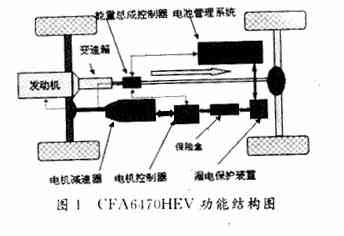

4.3 CAN interface software design 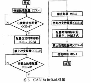
4.3.2 Sending data 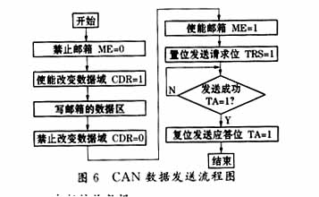
4.3.3 Interrupt receiving data