Overview: 1 Overview Today's portable terminal products such as smartphones and portable routers are moving toward smaller, thinner and lighter weights. However, as the processing power of portable terminal products continues to increase and the functions are continuously enriched, the power consumption is increasing. Before the battery technology was broken, the dual-battery solution for the main battery and the backup battery became a better solution for extending the standby time. The main battery is designed inside the casing and is in a constant state. The backup power is designed outside the casing and can be inserted and removed at will. Based on the structural characteristics of the main battery and the backup battery, the design requirements of the dual power supply scheme mainly include the following two aspects: Low-Voltage Motor,Automotive Industry Pump Motor,Oil Pump Motor,Hydraulic Pump Motor Shaoxing AnFu Energy Equipment Co.Ltd , https://www.sxanfu.com
With the continuous improvement of the processing power of portable terminal products and the continuous enrichment of functions, the power consumption of terminal products is also increasing, so standby time becomes one of the key performance indicators of products. Since the portable terminal device is limited in size, it is not possible to extend the standby time simply by continuously increasing the capacity of the single-cell lithium battery. Therefore, the dual-battery power supply scheme of the main battery and the standby battery is not preferable as a preferred solution for extending the standby time. This paper introduces the design of the dual battery power supply scheme based on the charging management chip bq24161 and the ORing control chip TPS2419. The design requirements of the dual battery power supply scheme are analyzed, and the design block diagram and schematic diagram are given. Based on this, the charging management circuit is analyzed. The specific design method of the ORing circuit, and the working principle of each part of the circuit is analyzed in detail. Based on the designed circuit, the performance indicators such as power supply reliability were tested. The test includes testing the reliability of the system during the insertion and removal of the backup power under static load current and dynamic load current conditions. The test results show that the scheme can ensure the reliability of the system power supply during the insertion and removal of the backup power, and can flexibly manage the charging management circuit. It is a dual-battery power supply solution suitable for a variety of terminal equipment.
1) The standby battery should ensure the reliability of the system power supply during the plugging and unplugging process;
2) The battery path and the main battery path do not affect each other;
3) Flexible charging management for the main battery and the standby battery.
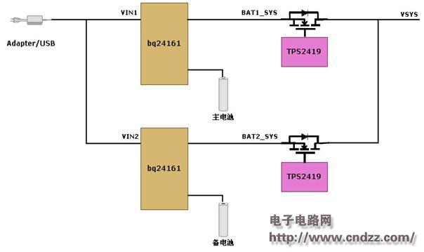
Figure 1 shows the block diagram of a two-battery powering scheme based on the bq24161+TPS2419. The charging management of the main battery and the standby battery are separately controlled by two charging management chips bq24161. The bq24161 is a highly integrated single-cell Li-Ion battery charge management chip with Dynamic Path Management (DPPM). The main processor communicates with the bq24161 via the bus to enable charge management of the main battery and the backup battery, including flexible control of charging current, charging voltage, status monitoring and control. The TPS2419 is an ORing circuit controller for N+1 powered systems. It is used with a low on-resistance N-channel MOSFET to provide ORing diode reverse current protection while achieving high efficiency of the MOSFET. The TPS2419 turns the corresponding path MOSFET on or off by detecting the supply voltage and the system voltage. On the one hand, the TPS2419 turns on the MOSFET in time to ensure the timeliness and reliability of the power supply to the system. On the other hand, the TPS2419 quickly turns off the MOSFET to prevent and reduce the system voltage to the input power supply. The redundancy design of the ORing circuit ensures that the main battery and the backup battery power path are mutually standby, and also ensures the safety and reliability of the system voltage during the power-on plugging process. 
(Please read the PDF for details)