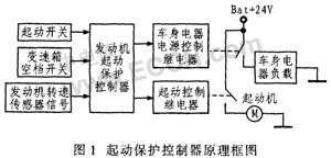
1 Introduction This article refers to the address: http:// The starting of the automobile engine is achieved by the starter driving the engine flywheel rotation. The starter driven by the battery drives the gear to generate mechanical motion; the transmission mechanism meshes the drive gear into the flywheel ring gear, and can be automatically disengaged after the engine is started; the start and stop of the starter DC motor is controlled by the electromagnetic switch. The car starter is a valuable part of the car and is easily damaged. However, in order to extend the life of the starter, proper use is required. Due to misoperation, etc., when the engine of the car is started, if the engine is started, the starter cannot be powered off in time. The starter will be burnt or the flywheel ring will be damaged; if the transmission is not in neutral when starting, it will cause traffic accidents and personal safety. In the process of starting the engine, the starter should draw 300-400 Ah from the battery. In order to prevent the battery from over-current or damage, the starting time should not exceed 5 s. In winter, it is easy to start difficult. Each start-up time should not be too long at start-up, and each start should be left at an appropriate interval. In order to achieve normal starting and safety protection of the engine, it is necessary to consider it from the automotive electrical control system. In the starting circuit system of the automobile engine, the power supply of the automobile starter comes from the battery, and the starter coil current is very large when the engine is started, reaching hundreds of amps. In order to ensure that the car engine can start normally, it is usually required to cut off the power supply of the vehicle body such as the car light when the engine is started, and only to provide power for the car starter. In order to prevent a safety accident when starting the car, the car engine can only be started when the gear shift position of the car is in the neutral state. Otherwise, the car will be displaced due to the momentary strong rotation of the starter. If there is an obstacle in front, it will be damaged. Car or endanger personal safety. In order to protect the starter, each start must not exceed a certain period of time. If the continuous start time of the vehicle starter with load exceeds 5~8 s, the start switch will not be disconnected after the engine is started, and the starter will continue to work, then the flywheel gear will drive the starter drive. The gear rotates at high speed, accelerating damage to the starter one-way clutch. If the start switch is turned on after the engine is started, the starter drive gear will collide with the high-speed rotating flywheel to damage the starter. Therefore, it cannot be restarted under the engine start condition. Here, an automotive start protection controller based on the NXP P89LPC901 microcontroller is introduced. The controller detects and controls the starting process of the automobile engine. By using the load power supply system one by one, the impact of the large starting current on the vehicle power supply is solved, and the gearbox position and engine speed are detected during the engine starting process. To achieve protection of the car starter. 2 start protector working process and function 2.1 Working process Figure 1 shows the block diagram of the car start protector. The working process is: the starting protection controller detects the starting switch. When the starting switch is turned on, if the transmission gear position switch is in the neutral position and the automobile engine is not in the working state, the body electrical power relay is turned on, and the vehicle body is cut off. After the electrical load power supply is delayed for 0.5 s, the start control relay is turned on, and the starter is energized to start. When the start switch is turned off or the engine speed reaches 300 r/min, the controller releases the start control relay, and the starter stops powering, and the delay is 0.5 s. The body electrical power relay is released, the body electrical load power is turned on, and the startup is completed.
This is the most competitive 15.6 inch Budget Business Laptop, comes with 2022 intel latest celeron cpu-N5095, J4125, etc . Of course, other Budget Working Laptop are also available.
For example, 15.6 inch i5 4th Budget Workstation Laptop for your mid-level task, 14 inch i5 10th Budget Laptop For 3d Modeling, 15.6 inch i7 5th Budget Laptop For Photoshop, or 15.6 inch i7 10th budget laptop for work, etc. Of course, there are other type device, like Android Tablet, 2 In 1 Laptop , Mini PC , All In One PC.
A thin, portable, light-performance laptop may be the ideal tool when people choose a business laptop, therefore just ask yourself 1.what jobs you mainly need this device to do, then choose the cpu and storage necessary, 2.if need fingerprint or backlight; 3. prefer type C charging? Or traditional DC is ok? 4. Does RJ45 webcam is important for you? 5. how many hours you need the laptop to work when do your main jobs?
6.Camera position, prefer on the middle of screen up? or is ok on the bottom of screen?
Budget Business Laptop,Budget Working Laptop,Budget Workstation Laptop,Budget Laptop For 3d Modeling,Budget Laptop For Photoshop Henan Shuyi Electronics Co., Ltd. , https://www.shuyicustomlaptop.com
2.2.1 Normal start 


Design of NXP P89LPC901 Single-chip Computer Start Protection Controller
2.2 main functions
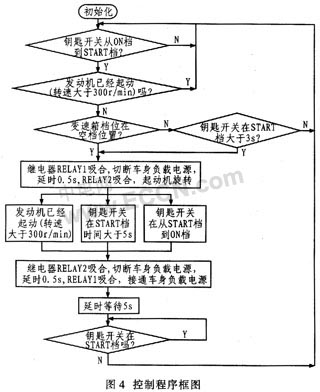
When the key switch is activated from the ON position to the (starting gear) START position to start the engine, when the transmission gear position is in the neutral position, the starting protection controller first cuts off the body electrical load power supply, with a delay of 0.5 s. Turn on the start relay again, the starter starts. When the starter drives the engine to rotate, the engine speed is greater than 300 r/min, or the key switch returns from the START position to the ON position, the controller controls the start relay to be disconnected, and the starter is powered off. , the delay is 0.5 s, and then the body electrical load power is turned on, and the starting process is completed.
2.2.2 Non-empty start protection
The starter protector requires the gearbox to start the engine only when it is in the neutral position. However, if the neutral switch is damaged or the driver knows that the transmission is not in the neutral position but must start the engine, the non-neutral position protection start can be adopted. The starting condition is that the key is required to be turned from the ON position to the START position and in the START position. It can be started after 3 s. The starting process is the same as the normal starting.
2.2.3 Key switch cannot be returned to protect
During the start of the car, if the key switch is in the START position and the time is greater than 5 s, or the key switch fails, it cannot be returned from the START position to the ON position within 5 s. In order to protect the starter and the battery, the controller can cut off. Starter power supply, turn on the body electrical load power.
2.2.4 Repeated start protection
If the engine is already in operation and the speed is greater than 300 r/min, when the key switch is turned from the ON position to the START position, the controller ensures that the starter is no longer activated.
3 P89LPC901 microcontroller main features
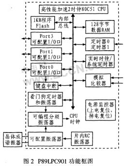
According to the working conditions and reliability requirements, after comparison, the single-chip package microcontroller produced by NXP is used, namely NXP P89LPC901 microcontroller. The operating temperature range of the MCU is -45 to 85 °C, so it can meet the application requirements of automotive start protectors. The main performance of this microcontroller is: due to the high-performance processor architecture and enhanced 8051 core. Its instruction execution speed is 6 times faster than the standard 80C51 device, so many system-level functions are integrated. Figure 2 shows the structure and functional block diagram. The chip integrates 1 KB Flash program memory, 128 B data memory, 2 16-bit timer/counters and PWM, 23-bit system timer, and enhanced UART with high precision internal RC oscillator and on-chip reset, 8 references The foot SO-8 package has a maximum of 6 programmable I/O ports, a programmable analog comparator, a programmable Watchdog timer and a power monitor. The MCU has a high performance-price ratio and can meet the requirements. The control function requirements of the car start protector.
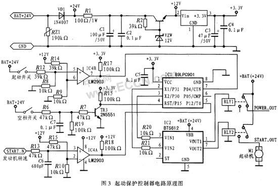
4 start protector circuit principle According to the function and working process requirements of the car start protector, the car start protector circuit using NXPP90LPC901 single chip is controlled by power supply circuit, single chip circuit, switch signal input circuit, engine speed input circuit, power relay and start relay Circuit and other components (see Figure 3). The P89LPC901 uses an internal reset circuit and an on-chip RC oscillator (7.373 MHz) to provide six programmable I/O interfaces for input detection and output control.
4.1 power circuit
Starter protection controller for passenger cars. The power supply uses a +24 V automotive battery power supply. After the varistor and the protection diode VD1 that prevents the polarity of the power supply from being connected, the voltage of +12 V is obtained. This voltage is the comparator LM2903 power supply, and the voltage is limited by the filter. After that, it is regulated and filtered by the HA7355 regulator, and then the voltage of +3.3 V is supplied to the P89LPC901.
4.2 switch input detection circuit
The input switches of the start protection controller are: start switch (START-SW), neutral switch (NULL-SW); two switch input signals, which are respectively connected to the positive power supply (+24 V).
The starter's power comes from the car battery. When the starter starts, the current is very large, up to hundreds of amps, which may cause the battery to lose power and reduce the voltage. In order to ensure that when the start switch is turned on, the battery voltage is greater than 12 V, it can start normally, so that the START-SW signal is converted by the comparator LM2903 and connected to the P04 pin of the microcontroller. When the START-SW signal voltage is greater than 12 V, the 7th pin of the LM2903 outputs +33 V. When the START-SW signal voltage is greater than +12 V, the 7 pin of the LM2903 outputs 0 V.
The neutral switch NULL-SW signal is converted into the level signal required by the single-chip microcomputer through the transistor conversion circuit, and the P15 pin of the single-chip microcomputer is connected. When the neutral switch is turned on, the P15 pin of the single-chip microcomputer is at a high level; when the neutral switch is turned When disconnected, the P15 pin of the microcontroller is low.
4.3 Engine Speed ​​Sensor Input Detection Circuit The engine speed sensor outputs a sinusoidal signal with a voltage range of 3 to 6 V. The engine output signal is 173 pulses per revolution. When the engine speed is greater than 300 r/min, the start is completed. The sinusoidal signal outputted by the engine speed sensor is converted into a square wave signal by the comparator LM2903 to the P12 pin of the single-chip microcomputer, that is, the counter input pin of the P89LPC901. When the signal output by the engine speed sensor is greater than 2 V, it is high level; Low at 2 V.
4.4 Relay Control Circuit
In the control circuit, the power supply of the vehicle body is controlled by the relay RLY1 to connect the load to the normally closed contact; the start control of the starter is controlled by the relay RLY2 to connect the load to the normally open contact. The relay in the circuit is output by P30 and P31 of 89LPC901 and amplified by BTS612.
5 start protection controller control program
The start protection controller control program is written in assembly language. Figure 4 shows a block diagram of a control sequence designed according to the starting process and functional requirements of the engine.
6 The design of the car start protection controller circuit takes into account the environment and reliability of the car. It is controlled by NXP 89LPC901 single-chip microcomputer. It has the advantages of simple control circuit design, flexible control, high reliability and low cost. It has already loaded more than 50,000 vehicles on Yutong Bus. It is proved to be stable and reliable and works well.