Design of Wireless Meter Reading Terminal Circuit Based on MSP43O and Zigbee
This paper introduces a wireless meter reading terminal based on Zigbee network with MSP430F149 microcontroller as the core. The main features, hardware circuit design and software design of the terminal are elaborated. The test results show that the design has the characteristics of stable operation and high reliability, and can be widely used in wireless centralized meter reading of various water, electricity and gas meter terminals, and has a good application prospect.
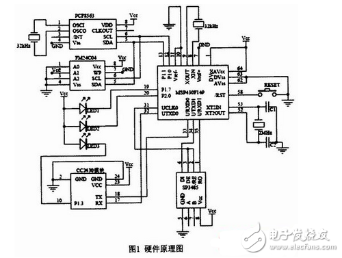
Circuit principle: The core processor uses TI's MSP430F149 microcontroller. In order to achieve low power consumption requirements, the circuit uses high-speed and low-speed two crystal oscillators, and the high-speed crystal oscillator generates MCL-K with higher frequency to meet the requirements of high-speed data operation of the CPU. When the CPU is not required to work, the high-speed crystal oscillator is turned off. The low speed crystal generates a lower frequency ACLK and runs the real time clock. The calendar clock chip uses the PCF8563 from PHILIPS. This chip supports IIC bus interface, adopts low-power CMOS technology, and has a wide operating voltage range of 1.0V to 5.5V. Under 3.0V power supply conditions, the typical values ​​of operating current and sleep current are 0.25μA. It can record the century, year, month, day, week, hour, minute and second, with timing, alarm and frequency output functions. The memory uses Fudan Microelectronics FM24C04. This chip is a two-wire serial EEPROM, compatible with IIC bus interface, using low-power CMOS technology, with a wide operating voltage range of 2.2V ~ 5. SV, rated current is 1mA under 3.0V supply, and sleep current is typically 5μA. In case of power failure, the data in the memory can be saved for 100 years.

MSP430F149 has two TTL level serial interfaces on the hardware. After one SP3485 chip is converted into RS485 serial interface, it communicates with the digital energy meter connected to the bottom layer, and the other directly communicates with CC2430. The RS485 bus is supported by most of the current digital energy meters. It uses balanced transmission and differential reception to achieve communication. It has strong anti-common-mode interference capability, signals can be transmitted over kilometers, and supports multi-point data communication. The CC2430 chip conforming to the Zigbee protocol supports a TTL-level serial interface, so it can communicate with the core processor without interface conversion.
All devices in the design process of the terminal are designed with low power consumption in mind. Even with battery power, the battery can be used for at least two years. And the selected components all support 3.3V voltage, all circuits only need a single power supply to run stably. Figure 1 is a hardware schematic diagram of the terminal, omitting the power supply voltage regulator circuit, the filter circuit and some peripheral components. LED1, LED2, and LED3 in the figure are used to indicate receiving data, transmitting data, and wireless network status, respectively.
High Voltage Laboratory Power Supplies
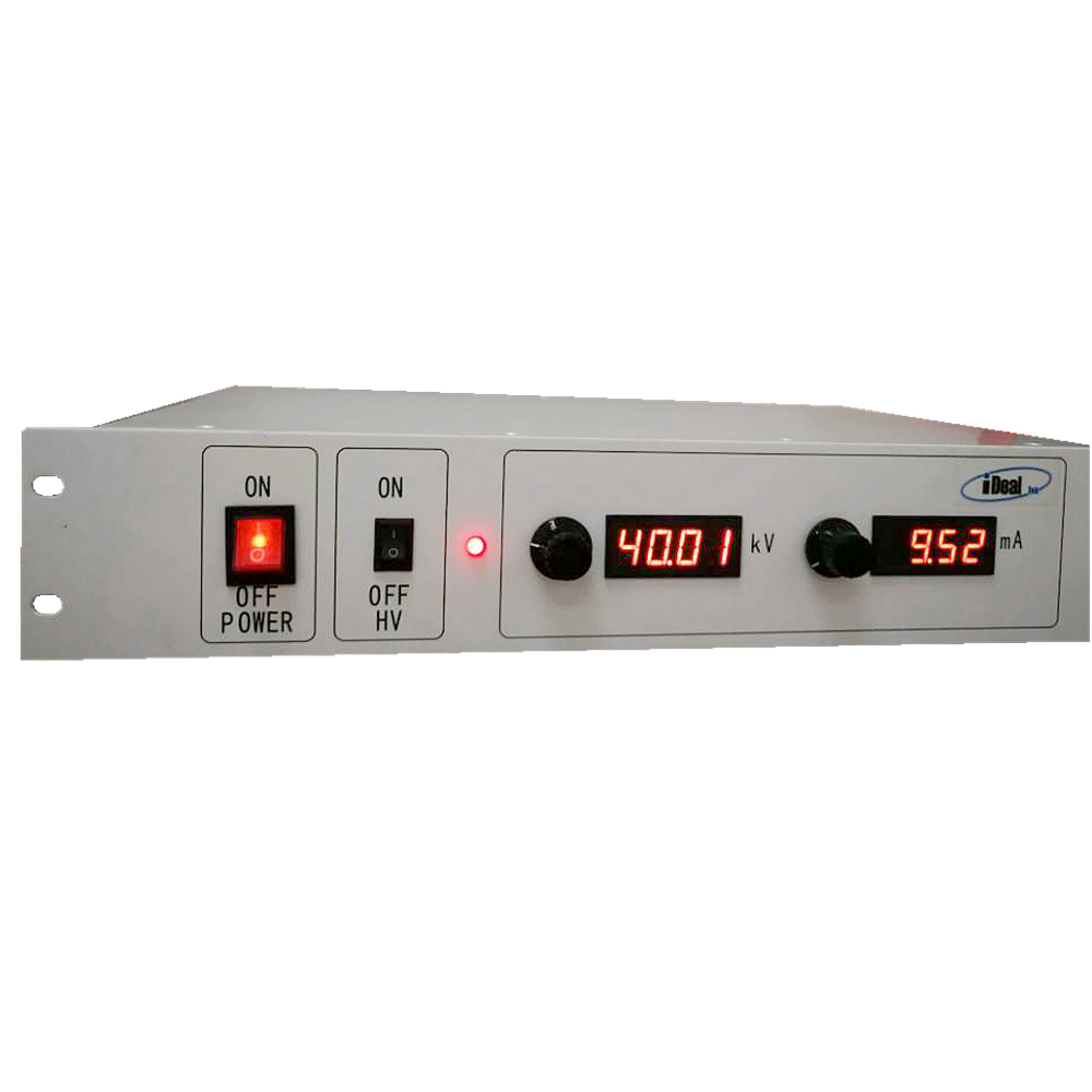
The LTP series laboratory high-voltage power supply is a high-voltage power supply specially designed for high-voltage laboratory applications with high precision, high stability, and low ripple output characteristics. Built in 19 inches, 2U standard chassis with designed output power at 1KW and output voltage ranges 1KV to 60KV.

After optimizing the output stability and output ripple on the basis of the 1KW high-voltage power module, the stability and ripple of the high voltage lab power supplies can reach the level at 0.1%.
The high-voltage laboratory power supply is also a constant-voltage and constant-current type high-voltage power supply. The output voltage and current can be continuously adjusted from 0 to the rated value via the added control potentiometers added to the front panel, high resolution LEDs display for output KV and mA are also added for intuitive measuring of high voltage laboratory bench.
The lab high voltage power supply is also equipped with DB9 interface as standard. Customers can apply 0-10V signals and dry contact signals to the interface according to our interface definition to achieve comprehensive control and monitoring functions on the power supply, like high voltage start / stop, output setting and reading.
The LTP series laboratory high voltage power supply is equipped with complete protection functions, which can deal with sparking, short circuit, overload, load discharge and other situations.
At present, the high-voltage laboratory power supply is mainly used in Laboratory power, High-voltage test stands, Electrostatics, Capacitor / Insulations testing and Electrophoresis applications.
High Voltage Lab Power Supplies, High Voltage Laboratory Power Supplies, High-voltage Lab Power Supplies, Laboratory High Voltage Power Supplies, Lab High Voltage Power Supplies
Yangzhou IdealTek Electronics Co., Ltd. , https://www.idealtekpower.com