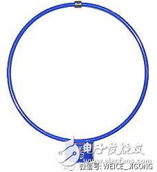
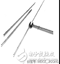
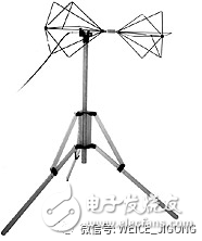
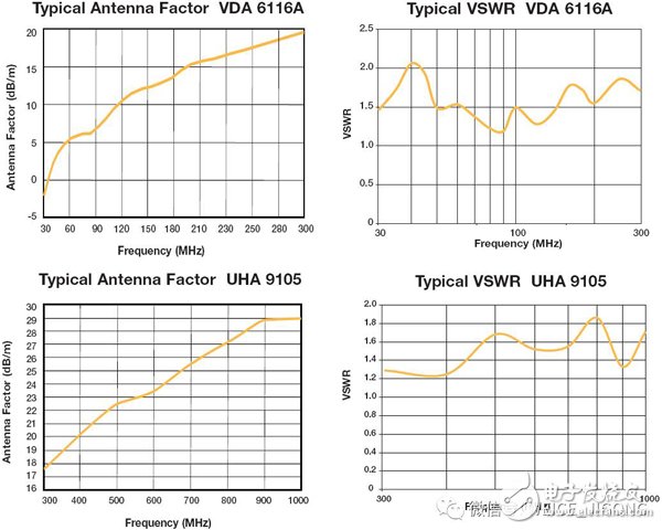
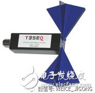
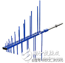
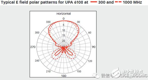
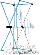
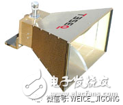
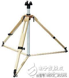
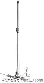
Electromagnetic Compatibility EMC is inseparable from testing. Irrespective of whether it is a radiation disturbance test or an anti-radiation harassment test, antennas other than EMI receivers, signal sources, and power amplifiers are required. An antenna can be used to transmit signals and receive signals. It is reversible and has reciprocity. It can be regarded as a transducer and is an interface device between the circuit and space. When used to transmit signals, the electromagnetic waves generated by converting the high-frequency signals generated by the signal sources into space are emitted in a certain direction. When used to receive signals, the electromagnetic waves in the space are converted into electrical signals and transmitted to the receiver through cables. The main parameters of the antenna include: frequency range, gain, antenna coefficient, pattern, power, impedance, voltage standing wave ratio, and so on. In the EMC test, according to different EMC standards, such as the general standard IEC61000-6-3 (residential and commercial environment) of radiation disturbance, IEC61000-6-4 (industrial environment), it is required to carry out radiation disturbance tests of different frequency bands and Anti-radiation harassment test. Specific to different product standards, such as: · Radio interference test for electrical lighting equipment: IEC/CISPR15, EN55015, GB17743 specifies that a radiation disturbance test from 9KHz to 300MHz is to be performed; for radio illumination immunity test of electrical lighting equipment, IEC61547, EN61547, and GB18595 provide for 80MHz to 1000MHz Radiation immunity test; · Radio interference test for household appliances: IEC/CISPR14-1, EN55014-1, GB4343.1 stipulate that radiated disturbance tests from 30 MHz to 300 MHz are to be performed; radio immunity tests against household appliances IEC/CISPR14-2, EN55014- 2. GB4343.2 specifies that a radiation immunity test from 80 MHz to 1000 MHz is to be performed; Radio interference tests for ITE information technology equipment, IEC/CISPR22, EN55022, and GB9254, stipulate radiation interference tests from 30 MHz to 1000 MHz. The basic standard GB/T6113.203-2008 specifies the measurement limits for 1 GHz to 6 GHz; the radio immunity test for ITE information technology equipment IEC/CISPR24, EN55024, and GB/T17618 specifies the radiation resistance to be performed from 80 MHz to 1000 MHz. Harassment test; Different product standards stipulate that different frequency bands should be tested. Different types of antennas are also used. To facilitate the selection, the common antenna types and coverage frequency ranges are summarized as shown in Figure 1. Figure 1. EMC test antenna selection Unipolar vertical antenna As shown in Figure 2, this antenna covers a frequency range of 9 KHz to 30 MHz, a height of 1 m, an antenna coefficient of +10 dB/m+-1.5 dB, and a maximum measured field strength of 1 V/m. With amplifiers, it is an active monopole vertical antenna and is mainly used for measuring electric field components from 9KHz to 30MHz. Figure 2. Unipolar vertical antenna Loop antenna As shown in Figure 3, this antenna covers a frequency range of 9KHz to 30MHz, inner ring diameter: 600 mm, antenna coefficient is 20 dB (typ), and maximum measured field strength: 137 dBμV/m (7 V/m ). With amplifiers, it is mainly used for measurement of magnetic field components from 9KHz to 30MHz. Figure 3, HLA 6120 loop antenna Dipole antenna As shown in Fig. 4, depending on the stretchable lengths, these two antennas cover the frequency ranges from 30 MHz to 300 MHz and from 300 MHz to 1 GHz. The length of this antenna corresponds to half the wavelength of the operating frequency, so the length needs to be modulated according to different frequencies in the measurement. Because fixed-frequency half-wave dipole antennas provide better performance, they are often used for antenna calibration and site attenuation measurements. Figure 4. VDA 6116A/UHA9105 Tuning Dipole Antenna Double cone antenna As shown in Figure 5, this antenna covers a frequency range from 30MHz to 300MHz. The frequency response curve for the specific parameters is shown in Figure 6. Applicable to CISPR/EN, FCC and MIL-STD standards testing. Figure 5, VBA 6106A biconical antenna Fig. 6 Frequency response curves of VBA 6106A parameters As shown in Figure 7, this compact biconical antenna covers a frequency range from 200 MHz to 1 GHz and is a dipole field strength measurement antenna. Typical antenna values ​​are: 20 dB/m ~ 32 dB/m; typical gain : -3.5 dB to +1.5 dB; typical VSWR: ≤2.0 (350 MHz to 1000 MHz). Figure 7. DPA 4000A biconical antenna As shown in Figure 8, this compact biconical antenna covers a frequency range from 800 MHz to 2.8 GHz and is a dipole magnetic field strength measurement antenna. Typical antenna values ​​are: 30 dB/m ~ 38 dB/m; typical gain : -2.0 dB to +1.5 dB; typical VSWR: ≤2.5 (1GHz~2.5GHz). Figure 8. DPA 3000 double-cone antenna Logarithmic antenna As shown in Figure 9, these two antennas cover frequency ranges from 300MHz to 1 GHz and from 200MHz to 1 GHz. Typical gain: 4 dB; Impedance: 50 Ω; Maximum continuous power: 300 W. The antenna pattern is shown in Figure 10. Suitable for CISPR/IEC/EN, FCC, MIL-STD and other standard tests. Figure 9. UPA6108/6109 Log Periodic Antenna Figure 10. Directional pattern of UPA6108 Composite antenna As shown in Figure 11, this antenna covers a frequency range from 30 MHz to 2 GHz. Typical Gain: 6 dB; Impedance: 50 Ω; VSWR: 1.5:1; Maximum Continuous Power: 200 W; Antenna Factor (Typical): 30 MHz: 20 dB/m; 60 MHz: 8 dB/m; 300 MHz: 14 dB/m; 500 MHz: 18 dB/m; 1000 MHz: 24 dB/m; 2000 MHz: 30 dB/m. Figure 11. UPA6192 Composite Broadband Antenna As shown in Figure 12, this antenna covers a frequency range from 26MHz to 3 GHz. Typical Gain: 6 dB (200 MHz to 3 GHz) / 8 dB (700 MHz to 2.5 GHz); Impedance: 50 Ω; VSWR: Maximum 2:1; Maximum Continuous Power: 600 W. Figure 12, CBL 6144 Composite Broadband Antenna Horn antenna As shown in Figure 13, this antenna covers frequencies ranging from 1 GHz to 18 GHz. Typical gain: 4~15 dBi; Impedance: 50 Ω; VSWR: Maximum 2.5:1; Maximum continuous power: 200 W. Figure 13, BHA 9118 Horn Antenna The antenna usually needs to be mounted on a tripod or an antenna mast to facilitate lifting and adjusting directions. In order to reduce the reflection and influence on the RF signal, these tripods or antenna masts usually use non-metallic materials. Figure 14 shows a BTP6020A tripod, made of fiberglass material, which can carry up to 50 kilograms. Figure 15 shows an antenna mast. Figure 14. BTP6020A antenna tripod Figure 15. CAM6330A antenna mast In addition to manual use in the EMC lab will also be used to automatically control the lifting device. There are many different kinds of antenna products for EMC testing. Here only some concrete objects are listed for each type of antenna to facilitate understanding and selection. Electromagnetic compatibility EMC testing will also use many test instruments, test accessories, including the use of methods, will be introduced later in time.
This is a special TOVAPO Z001-1500 Vape Pen product series. We sell Tovapo Z001-1500 vape pen disposable,Z001-1500 vape pen kit, Z001-1500 vape pen disposable,Z001-1500 vape pen kit,Z001-1500 vape starter kit,850mah vape pen,850 mah vape disposable Ningbo Autrends International Trade Co.,Ltd. , https://www.supermosvape.com



Z001-1500 vape starter kit, and other Tovapo vapes.
We are specialized electronic cigarette manufacturers from China, Vapes For Smoking, Vape Pen Kits suppliers/factory, wholesale high-quality
products of Modern E-Cigarette R & D and manufacturing, we have the perfect after-sales service and technical support. Look forward to
your cooperation!