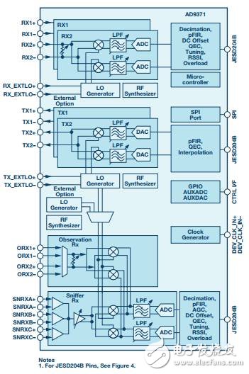
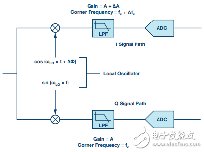
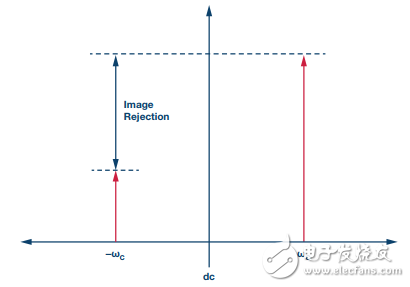
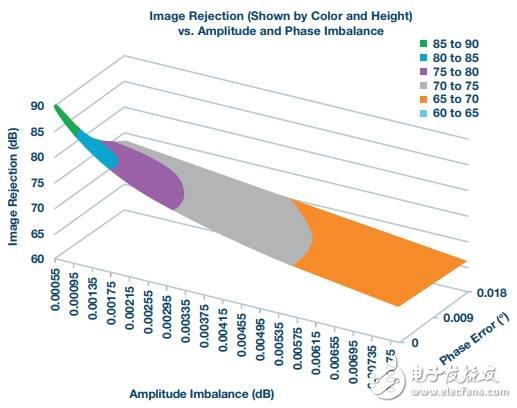
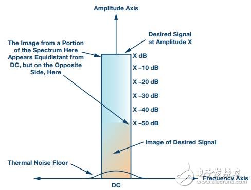
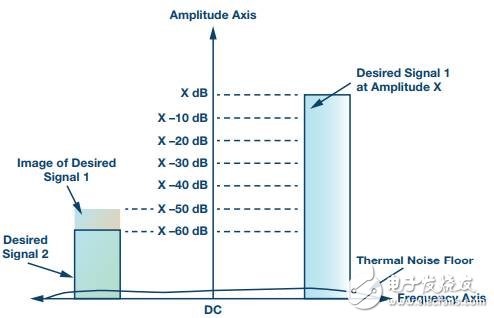
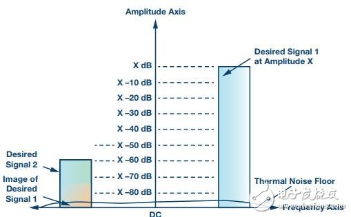
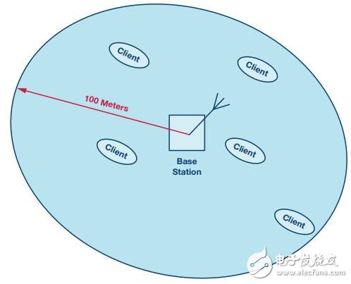
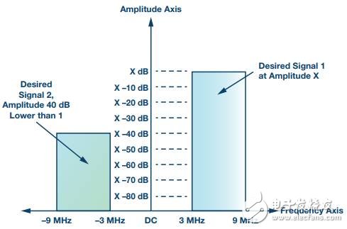
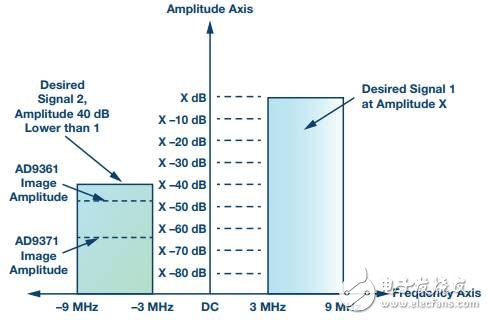
Mirror mirror, in the face of the AD9361 and AD9371 transceivers that offer unparalleled integration, numerous features, and a large number of user-selectable options. Who should I choose? In addition to the large differences in performance levels and power consumption of the AD9361 and AD9371, image rejection is one of the features that distinguish between the two series. Today I will talk about "mirror suppression and its impact on the desired signal"~ After reading it, I hope that you will no longer be entangled in who you choose. Image suppression basics Both the AD9361 and AD9371 families use zero-IF (also known as zero-IF or ZIF) architectures for extremely high levels of integration and significantly reduce the number of frequency-related components in the system. As shown in the functional block diagram of the AD9371 in Figure 1, the primary receive signal path and the primary transmit signal path use a complex mixer stage with a radio frequency (RF) centered at the local oscillator (LO) frequency and a DC-centered baseband. Convert between. Figure 1. Functional block diagram of the RadioVerse AD9371 transceiver Despite the many advantages offered by such high integration, ZIF radios present challenges. The complex mixer has an in-phase (I) signal and a quadrature-phase (Q) signal. Once any mismatch in the phase or amplitude of these signals occurs, combining the upconverted I and Q signals results in summation and cancellation performance degradation. This is described in the article cited above. When the desired signal is transmitted, imperfect cancellation results in an inverted copy of the signal on the opposite side of the signal's local oscillator (LO) frequency. This copy of the signal is called a mirror and is much smaller than its corresponding desired signal. Similarly, when the desired signal is received, an inverted copy of the desired signal will appear on the opposite side of the signal's DC. In other architectures (such as superheterodyne architecture), mirror filtering can be performed at the intermediate level. The main advantage of the ZIF architecture is the removal of these filters and intermediate mixer stages, but this requires excellent I and Q balance to reduce the image amplitude to an acceptable level. The simplified schematic diagram of the received signal path in Figure 2 shows where these mismatches occur with the mismatches specified by ∆A, ∆fC, and ∆φ. Only one path shows the phase of the mismatch because it is an imbalance between the signal paths that form the image, not the absolute gain and phase of the signal path. Therefore, it is mathematically correct to display all the imbalance factors in one path. The complex mixer shown in Figure 2 is also referred to as a quadrature mixer because the two LO signals provided to the mixer are orthogonal to one another. Figure 2. Orthogonal receiver signal path with simplified display signal impairments Figure 3 illustrates a useful signal using a single tone or continuous wave (CW) and the resulting unwanted CW image. The useful signal is downconverted to frequency ωC. If the orthogonal balance is not perfect, the image will appear at a frequency of -ωC. The image rejection ratio (IRR) is the difference between the wanted signal and the unwanted image signal, expressed in decibels (dB). The way to reduce the quadrature mismatch is called quadrature error correction (QEC). Figure 3. Monophonic useful signals and interference mirrors The image amplitude is related to the gain and phase mismatch, and the relationship is as follows: Where: ∆ = amplitude imbalance (expressed in decibels (dB), ideally 1) θ = phase error (expressed in degrees (°), ideally 0) Dimensional matrix equation can be derived, because the two input variables are cause performance degradation of image rejection. Figure 4 shows a portion of the matrix in which the axis across the entire page is amplitude imbalanced, the axes entering the page are phase imbalanced, and the vertical axis is image rejection (in dB). For example, if the amplitude error is 0.00195 and the system needs to achieve 76 dB image rejection, the phase error must be better than 0.01286°. Even in a single integrated circuit device, it is difficult to achieve image rejection better than 50 dB by controlling all factors that affect I and Q matching. The AD9371 typically achieves 76 dB of image rejection, which requires digital algorithms to control the analog path variables and apply corrections in the digital domain. Figure 4. Relationship between image rejection (in dB) and amplitude imbalance (in dB) and phase imbalance (in °) The effect of mirroring on useful signals Figure 5 is a simplified diagram showing the single-carrier situation where the waveform is centered on DC after downconversion . An example of this waveform would be a single instance of a 20 MHz LTE downlink OFDM signal. As shown in Figure 5, a portion of the useful signal on the negative side will have a mirror image on the plus side, and vice versa. In the case of a single-carrier centered on DC, the image is within (or above) the wanted signal and destroys the useful signal. Figure 5. Single modulated carrier with interference mirroring When a signal is received and then demodulated, there will be several signal impairments. Increasing the thermal noise of the noise floor of the received signal path is an example. If the image is within the useful signal, it will also increase the noise. If the sum of all noise sources is too high, the signal cannot be demodulated. The thermal noise floor shown in the single-carrier and multi-carrier diagrams is an example and is ignored as a contributing factor in these discussions. When using the AD9361's internal LO (for reference clock sources with recommended performance), the AD9361 will achieve an EVM of approximately -40 dB with no noise floor limitations. The EVM is limited to -40 dB by the phase noise of the RF PLL. The image rejection performance of the AD9361 of approximately 50 dBc means that in the single-carrier case shown in Figure 5, only the mirror can only reduce the EVM by approximately 0.5 dB. Such a low EVM reduction means that the transceiver is typically not a limiting factor for 64-QAM (or even higher) modulation schemes. In this single-carrier case, the image is always about 50 dB smaller than the useful signal, as shown in Figure 5. Figure 6 shows an example of multi-carrier. The wanted signal in the figure has a dc offset after downconversion. Figure 6. Signal 1 corrupts signal 2 causing the multi-carrier modulated signal to have an interference image The image of each useful signal is reflected by DC and displayed on the opposite side of the spectrum. In this example, the two useful signals have been downconverted to the same dc offset, with the useful signal 1 on the positive side and the useful signal 2 on the negative side. It should be noted that the amplitude of the useful signal 2 is 60 dB lower than the amplitude of the useful signal 1. The fact that two carriers have different amplitudes is common in multi-carrier situations, which can occur if signals from two mobile stations travel to the same base station with different amounts of path loss. This can happen if the distance between the two mobile stations is different from the base station, or if one of the mobile stations transmits a signal through or around another object other than the mobile station. The amplitude of the useful signal 2 is 10 dB lower than the amplitude of the image of the wanted signal 1. This means that the signal to noise ratio of the useful signal 2 is -10 dB. Even with the simplest modulation techniques, it is difficult to achieve demodulation. Obviously, better image rejection performance is needed to deal with these situations. Figure 7 shows the same situation, but with the typical receive image rejection performance of the AD9371. Figure 7. Signal 1 amplitude is lower than signal 2 amplitude resulting in multi-carrier modulated signal with interference mirror The amplitude of the wanted signal 1 image is now 15 dB lower than the amplitude of the wanted signal 2. Therefore, the signal to noise ratio is 15 dB, which is sufficient to demodulate the useful signal 2 using various modulation schemes. Technology to reduce orthogonal imbalance in AD9361 and AD9371 Both the AD9361 and AD9371 optimize the analog signal and LO path, essentially reducing the quadrature imbalance. But as mentioned above, the benefits that silicon can bring are limited. Digital correction can increase image rejection performance by several orders of magnitude. The AD9361 receiver quadrature calibration uses an algorithm to analyze the entire spectrum of data received to create an average correction over the entire bandwidth. For single carrier use cases and relatively narrow bandwidths (such as 20 MHz), this correction produces good image rejection over the target bandwidth. This is called a non-frequency correlation algorithm. The algorithm performs operations on the received data and updates it in real time. The AD9371 runs a receive image suppression calibration during initialization by injecting test tones and during operation using the actual received data. These more advanced calibrations can be adjusted based on frequency dependent imbalances and non-frequency related imbalances. The algorithm will be updated in real time. The AD9371 uses more advanced algorithms and circuit implementation corrections to outperform the AD9361 over the occupied signal bandwidth, with a difference of approximately 25 dB. This article describes the origin and impact of quadrature imbalance using the received signal path, but the ZIF transceiver must also overcome the same problem in the transmit signal path. When the signal path or LO path is unbalanced, the output of the transmitter includes the useful signal and its image. For the signal path - The AD9361 uses initialization calibration to reduce the quadrature imbalance provided by the optimized hardware design. Initialization calibration uses a CW tone that is at a single frequency and uses a single attenuation setting. This algorithm typically results in a power image that is about 50 dB lower than the useful signal. Another way to write is -50 dBc (below the decibel value of the carrier). Operating at over temperature, wide bandwidth, or different attenuation settings may affect the mirror level. The AD9371 performs initial transmit path calibration using a plurality of internally generated tones distributed over the useful signal bandwidth and determines the correction coefficients across multiple transmit attenuation settings. During operation, the transmit signal path tracking calibration uses the actual transmitted data and periodically updates the correction factor. The AD9371's image rejection performance is better than the AD9361 (the difference between the two is about 15dB), and this advantage is reflected in over-temperature and attenuation conditions and in the occupied signal bandwidth. Specific simplified example So far, based on the full content of this article, let's think about the experiment, assuming we are building a system that contains a central base station and multiple client devices. To simplify the example, this hypothetical system is running away from objects such as buildings that can cause multiple paths. The base station will communicate with client devices whose coverage area can be extended to 100 meters, as shown in Figure 8. Figure 8. Image showing the cellular coverage area of ​​the base station and the client base station The system will use multiple simultaneous 6 MHz wide carriers over a total bandwidth of 18 MHz. So in this system, a client device may be very close to the base station, such as 0.3 meters, and the distance between the farthest client device and the base station is of course 100 meters. The free space path loss difference between the two is about 50 dB. It is also assumed that the base station baseband processor can measure the received power and then inform the client to increase or decrease the transmit power by up to 10 dB. The nearby client will reduce the transmit power by 10 dB, while the farthest client will transmit at full power. The base station's received power is therefore reduced by 10 dB, resulting in an overall potential difference of 40 dB, as shown in Figure 9. The two carriers shown represent the worst case described above. For the sake of clarity, an optional carrier that can reside between two useful signals is omitted. Figure 9. Example of a multi-carrier modulated signal In this system, it is assumed that the base station and the client use the same transceiver - If the AD9361 is used, the amplitude of the transmitted image may be about 50 dB lower than the amplitude of the wanted signal. The receiver will also add similar image power. The two orthogonal imbalances combine to form a mirror image that is about 47 dB lower than the useful signal. If the AD9371 is used on both ends of the link, the amplitude of the transmitted image typically drops by 65 dB, and the receiver makes the image 75 dB lower than the wanted signal. Adding the two together gives a total mirror image that is about 64.5 dB lower than the useful signal. Figure 10 shows two results. Figure 10. Example of AD9361 and AD9371 Multicarrier Modulation Signals with Different Mirror Amplitudes In this simplified example, we only consider the effects of mirroring, ignoring the effects on SNR, such as thermal noise, phase noise, and nonlinearity. Among them, AD9361 can achieve SNR of about 7dB, while AD9371 can achieve SNR of about 24.5dB. If a complex modulation scheme such as 64-QAM is used in the system, the AD9371 may be the best choice due to overall system SNR requirements. If you use a simpler modulation scheme such as QPSK, then you can choose AD9361, which is more than enough. The technique used in the baseband processor will determine the actual system SNR required to demodulate the signal. Of course, from this thinking experiment to a real system, the effects of previous neglect such as thermal noise must be considered. The illustration and description of the two transceiver orthogonal correction algorithms previously given focus on the receive signal path. For the same reason, the effects of interference mirroring also apply to the transmission path. A transmit image located above a smaller carrier is equally cumbersome for the base station receiving the signal. The section describing the technology used by the transceiver to reduce the level of mirroring shows the quantitative differences achieved by two different device families. The magic mirror gives the conclusion that - The system design was performed according to the specific example above, and the design decision range was narrowed down to some short SNR related problems required to demodulate the received signal. While the imaging performance of the AD9371 family is always better than the AD9361 family, the AD9371 family consumes more power and uses a high-speed serial interface, which requires system engineers to view all aspects of the design and find the best solution for their application . 500 Portable Power Station,Lifepo4 Portable Power Station,Economical Portable Solar Power Station,Portable Power Station For Camping 500W Jiangsu Zhitai New Energy Technology Co.,Ltd , https://www.jszhitaienergy.com


