This charger can charge 3.6V1300mAh lithium battery, No.5 and No.7 NiMH batteries. In addition, this circuit can also be used as a regulated power supply for 1.5V or 3V retractable machines. The charger can automatically charge from fast charge, slow charge, constant voltage charge, and finally to trickle charge. The circuit eliminates the control components necessary for high-current charging, reduces the cost, simplifies the circuit, and is easy to manufacture and debug. The circuit is shown in the figure above, and the figure below is the printed board. Vacuum Furnace Insulation Screen Vacuum Furnace Insulation Screen,Thick Hard Felt Disc,Thick Vacuum Furnace Plate,Thermal Insulation Screen For Vacuum Furnace HuNan MTR New Material Technology Co.,Ltd , https://www.hnmtr.com
Working principle: The charger circuit is essentially a low-dropout regulated power supply. The upper part of the circuit is charged by the lithium battery, and the lower part is charged by the 1.2V nickel-hydrogen battery. The charging principle is the same. Transistor VT1 is a regulating tube. VT2, VT3 constitute an error amplifier. LED1 (two diodes in the lower half of the circuit) is used as the reference voltage and power supply indication. The output voltage of the charger is 4V. When the lithium battery is at 2.8V, due to the current limit of R5 and the maximum charging current is 300mA, the voltage drop across the VTLec is only 0.15V, and no heat sink can be added. The charging current drops as the battery voltage increases, and finally enters the trickle charge state. For the charging of imported lithium batteries, the foreign circuit charges the lithium battery to about 3.8V, so the output voltage is adjusted to 4V; if it is a domestic lithium-ion battery, it should be adjusted to 4.2V. The charger is not afraid of short circuit. When the output terminal is short-circuited, the maximum current is 500mA, and the voltage drop of VTLec is 0.1V, so it is still safe for VT1. 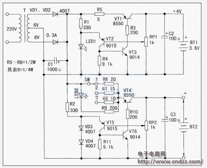
Simple and easy to charge multi-function charging circuit
The lower half of the circuit charges 1 to 3 of No. 5 and No. 7 NiMH batteries, and the maximum charging current is about 220 mA. The switch Sw is placed at 1, 2, and 3 to charge 1-3 batteries, and the corresponding output voltage should be adjusted to 1.3V, 2.6V, and 3.9V. When charging, LED2 lights up, and the brightness of LED2 fades as the battery voltage rises. When LED2 goes out, the battery enters trickle charging.
Use this circuit as the power supply for the radio and receiver, and adjust the output voltage of the upper half of the circuit to the required voltage of 1.5V or 3V. If it is not adjusted to 1,5V, change LED1 or use 2 diodes instead. Circuit performance: When the output is 1.5V, 300mA, the voltage drops by about 0.1V; when the output voltage is 3V, 300mA, the voltage drops by about 0.2V.