20553 pure class A power amplifier driven by NE5532 in parallel There are many well-made power amplifiers abroad, and the output power is not large, but its sweet and elegant music is often unmatched by many high-power amplifiers. [Circuit principle] Follow WeChat Download Audiophile APP Follow the audiophile class related suggestion The principle of the field effect tube to control the working current is completely different from that of ordinary transistors, which is much simpler than ordinary transistors. The five-pole power amplifier tube FD422 is used to make a single-ended Class A power amplifier. The design of this circuit is based on the principle of "simpleness first", which can reduce installation errors. Follow first ... 845 single-ended Class A amplifier circuit diagram will be 6N8P What is a pure Class A amplifier The so-called Class A or pure Class A amplifier is actually two sub-classes of the power amplifier classified by static operating point. According to this division, ... Field effect tube characteristics and the artistic charm and evaluation of the production of audio amplifiers with single-ended Class A amplifiers Audio amplifiers can be divided into electronic ... Single-ended Class A power amplifier circuit Below, we introduce a single-ended pure ... A 20W single-ended pure class A power amplifier circuit diagram, the circuit is very simple, used yuan ... Circuit characteristics 1. This power amplifier uses a current negative feedback circuit (Japan's famous golden voice most power amplifier ... The power amplifier made with the voltage regulator set is a pioneering idea for electronics enthusiasts ... This is a Class A power amplifier with an output power of 18W. The final stage uses a current series negative feedback circuit (the bypass capacitors at both ends of the output stage self-sufficient bias resistor are cancelled) ... Many audiophiles are happy to make power amplifiers, but most of them are limited to some single-chip sets such as LM1875, LM3886, LM4766, TD ...
The power amplifier introduced in this article, although its components can be used in general, and its output power is only 20W, but its musical expression is extremely outstanding, especially for the replay of classical music. 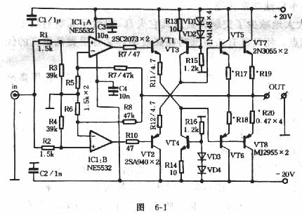
The circuit is shown in Figure 6-1. Two sets of independent operational amplifiers (NE5532) are used in the local circuit to form two complete single-ended amplifiers. They all work in pure class A mode, and each independently constitutes a full Waveform amplifier. The amplified signal is then organically mixed at the output point, effectively reducing the odd harmonic distortion that is extremely harmful to the sound quality. The bipolar diodes (VT1 and VT2) of the excitation stage, as current control devices, directly draw the required base current from the output of the op amp, which is an ideal way to use. VT3 and VT4 are used as the constant current source load of VT2 and VT1 respectively, which guarantees the stability of the whole machine and also makes the machine free from troublesome debugging procedures.
The VT1 and VT2 of the excitation stage and the two high-power transistors of the output stage constitute a cross-coupling mode. Due to the clamping effect between the working points of the diodes, the stability of this circuit is excellent, and there will be no inrush current sound when the power is turned on. Another benefit of cross-coupling is that the excitation stage and the output stage request operating current from the positive and negative power supply terminals, which is very beneficial to improve the common mode rejection ratio of the amplifier. The working current of the excitation stage is up to 85mA, and the working current of the output stage is as high as 1.7A (two tubes in parallel). Due to the large current of this machine, each transistor (including excitation stage and constant current source load transistor) must be equipped with a sufficiently large heat sink, and the power transformer must have sufficient margin (recommended 150W) . Because this machine has strong adaptability to the power supply, the power circuit only needs simple rectification and filtering. Those with conditions can add 1 ~ 2H inductance in the power supply loop to get better results. 


'+ data.username +'
[Photo] NE5532 20W pure class A amplifier driven in parallel
Interesting and informative information and technical dry goods
Create your own personal electronic circle
Lock the latest course activities and technical live broadcast
comment
Publish
Field-effect tube characteristics and the whole process of single-ended Class A amplifier
Posted at 2012-02-29 11:12 • 8287 times read
Making Single-Ended Class A Amplifier with Five-pole Power Amplifier FD422
Published in11: 01 2012-01-12 • 5901 views
845 single-ended Class A power amplifier circuit diagram (including power circuit)
Posted at 2009-12-20 23:43 • 2923 views
What is a pure class A amplifier
Posted at 2009-12-15 10:38 • 13170 views
Field effect tube characteristics and single-ended Class A power amplifier production
Published on 2009-11-10 08:57 • 3283 views
Single-ended Class A amplifier circuit
Published on 2009-05-16 07:51 • 3504 times read
20W single-ended pure Class A amplifier
Published on 2006-04-17 23:29 • 1195 times read
Meishun ME-308 pure DC current negative feedback type A amplifier
Posted at 2006-04-17 23:25 • 1690 views
Class A power amplifier made with three-terminal LM317
Posted at 2006-04-17 23:24 • 633 views
18W Bile Field Output Class A Power Amplifier
Posted at 2006-04-15 13:08 • 410 views
[Photo] Make beautiful sound class A amplifier
Published on 2006-04-15 13:05 • 3404 views