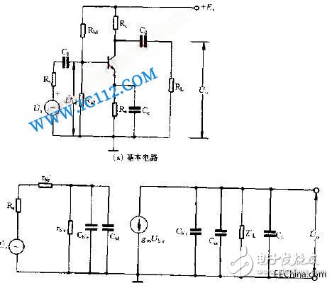
The amplifying circuit is also called an amplifier. It is the basic circuit that constitutes other electronic circuits. It is a circuit formed to amplify weak signals. The amplifying circuit can be divided into low frequency, intermediate frequency and frequency modulation according to frequency; according to the strength of the output signal, it can also be divided into voltage amplification and power amplification. It is the most complicated and changeable circuit in the circuit, so beginners should understand and master the following knowledge. (1) The amplifying circuit is an energy converter, it is impossible to create energy. The transistor uses a small change in the base current to control the collector current to make a big change. The electron tube and the field effect tube use a small change in the grid voltage to control the screen current to make a big change. Therefore, the field effect tube and the electron tube It is a voltage control device, and the transistor is a current control device. Unlike a magnifying glass, the magnifying circuit directly magnifies the text or object being viewed. The amplifying circuit superimposes the AC signal on the DC signal, the change of the AC signal causes the change of the DC signal, and then the change of the DC signal is converted into the change of the AC signal through the load resistance. The transistor in the amplifying circuit plays the role of this conversion. The small change in the base current controls the larger change in the collector current, which is equivalent to amplifying the base current. Yuankun Zhizhi Workshop is a comprehensive high-tech enterprise specializing in printed circuit board/PCB fast proofing, double-sided, multi-layer board large, medium and small batch production, while providing BOM quotation, SMT welding and components one-stop service. (2) There are both DC and AC components in the amplifier. For the convenience of circuit analysis, the path through which the DC component passes is often referred to as the DC path, and the path through which the AC signal passes is referred to as the AC path. Because the capacitor has the function of blocking DC and passing AC, when drawing the DC equivalent circuit, the capacitor should be regarded as an open circuit, and the others remain unchanged. When analyzing the DC path, it is necessary to return from the positive pole of the power supply to the negative pole of the power supply to form a closed path; when drawing the AC equivalent circuit, the capacitor should be regarded as a short circuit. The DC power supply will not change because the voltage at both ends will not change, and there is no AC. The voltage drop is also regarded as a short circuit, and the others remain unchanged. When analyzing the communication path, it is not necessary to repeat the analysis at each level, but to grasp where the entire signal comes from, through which components, what changes have taken place, and where it finally arrives. (3) The amplifying circuit usually has two working states: static and dynamic. Static means that when the input signal is zero, the DC power supply provides a suitable DC working voltage to each electrode of the triode, so that the triode can work in the amplifying area. That is to say, the external condition of the triode amplifying is the forward bias of the transmitting junction and the reverse bias of the collector junction. . Dynamic refers to the main analysis of the amplifier circuit's ability to amplify the signal after the input signal is added to the input of the amplifier circuit. Therefore, when analyzing the amplifier circuit, first static and then dynamic, that is, analyze the static DC path first to see whether the working voltage of the transistor, electron tube, and field effect tube is normal. After the static operating point is normal, analyze the dynamic AC path. The AC path and the DC path coexist in the same circuit, and they are not only related to each other, but also different from each other. The AC signal voltage is superimposed on the DC operating voltage, and the AC performance of the circuit is affected and restricted by the DC operating point. If the DC bias voltage is unstable or malfunctions, the AC path will be affected and malfunction. (4) The output signal amplitude increases in the negative feedback circuit, and the main reason for the distortion failure phenomenon is that the negative feedback element in the amplifier circuit is damaged, and the negative feedback effect disappears, which makes the gain of the amplifier increase, resulting in an increase in the output signal amplitude. At this time, focus on checking whether the negative feedback components in the circuit are open, soldered, or changed in resistance. If the output signal is distorted, it means that the amplifier is already working in the non-linear region (saturated or cut-off state). The working point voltage of the amplifier should be measured to find out whether the resistance in the circuit is normal and whether the parameters of the amplifier tube have changed.
Toggle switches
Toggle switches, also called On Off Toggle Switches, is often used as the switching device of the equipment stalls. Meanwhile, we are also offer our customers Key Switches, Metal Switches, Automotive Switches, Push Button Switches, etc.
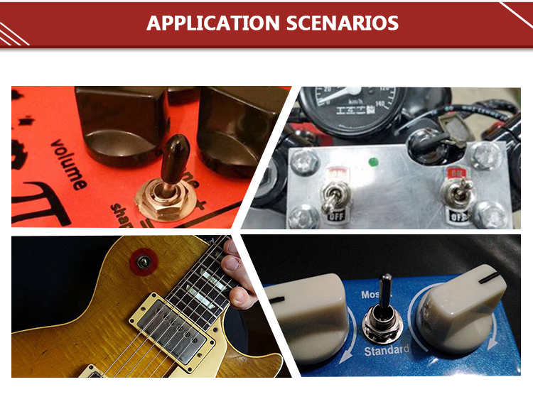
The Electrical Toggle Switches is a manually controlled Toggle Switches similar to the dial switch. Most of this Latching Toggle Switches are widely used in on-off control of AC and DC power circuits, and are less commonly used in circuits of several kilohertz or up to 1 megahertz. Let's take a look at the following.
1. Splash-proof knob button switch
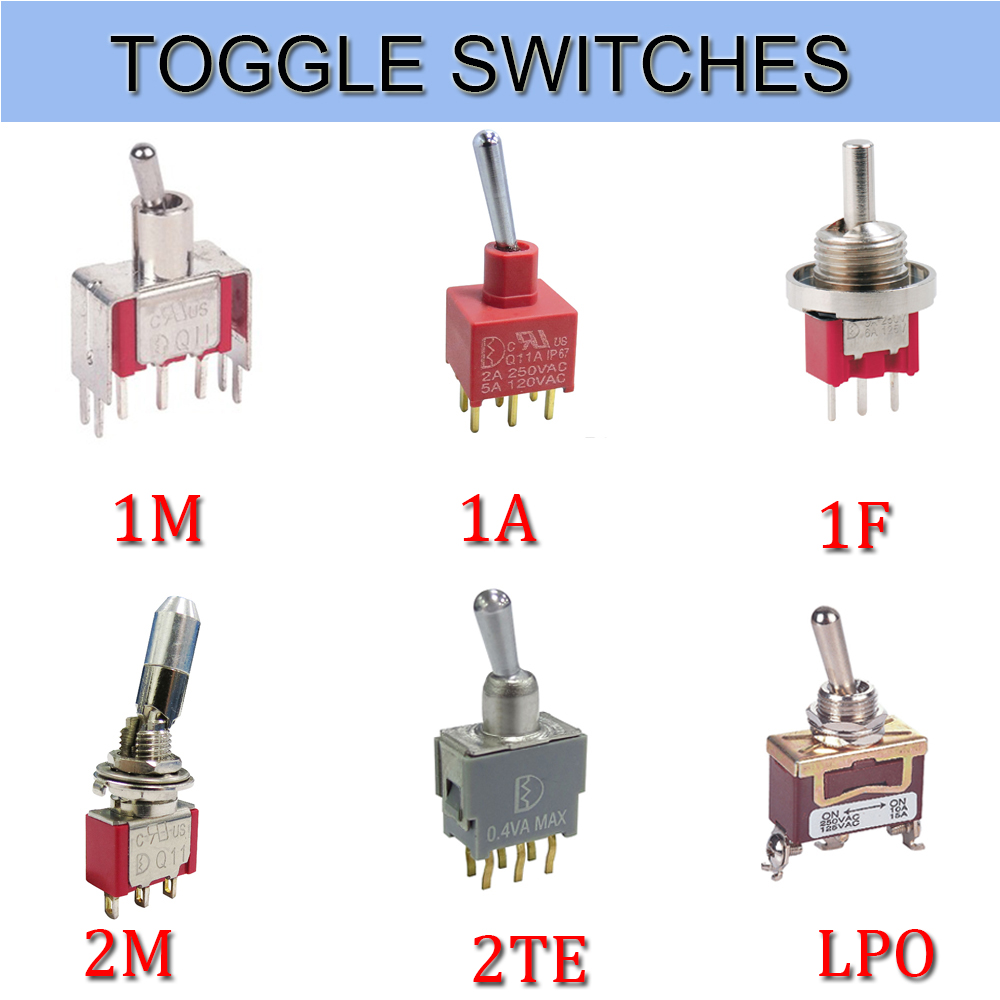
The panel is installed with a splash-proof `O` ring seal, and the knob is a ball. It is a splash-proof ball button knob switch. Its terminals are in a straight line and the bottom of the terminals is sealed with epoxy resin. Strong corrosion resistance, suitable for automotive parts
2. Vertical Mount Right Angle Toggle Switch
The vertical mounting of the terminals and the terminal pins are right-angled, so it is a vertically mounted right-angled toggle switch. Its contacts are gold-plated and highly reliable. Mostly used in anti-theft devices, alert system.
3. Bipolar single toggle switch
At the same time, the switch breaks the phase line and the N line and controls one branch. Therefore, it is a bipolar single toggle switches. The contacts are in 3PDT form and are used for multimedia speakers and stereos.
4. Standard surface mount unthreaded toggle switches
The terminal adopts the standard mounting mode. Its sleeve has no thread. It is called a standard surface mount screw-less switch. The contacts are SPDT and its electrical life is as high as 55,000. Used for medical equipment
5. Horizontally mounted right-angle toggle switch
Compared to the vertical switch, it only changes direction to horizontal, so it is horizontally mounted right-angle toggle switch. The contacts are double-pole double-throw and the bottom of the terminal is Epoxy Seal. Mostly used for computer peripherals.
Toggle Switches,Toggle Switch On Off,Toggle Switch Autozone,Toggle Switch Home Depot YESWITCH ELECTRONICS CO., LTD. , https://www.yeswitches.com

