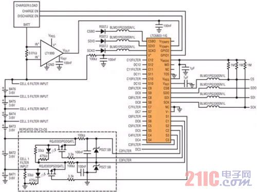
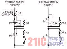
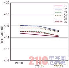
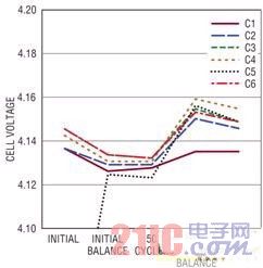
introduction This article refers to the address: http:// As batteries become more popular as power supplies, there is an equally strong demand to maximize battery life. Battery imbalance (that is, the state of charge mismatch of the cells that make up a battery pack) is a problem in large lithium-ion battery packs, which is caused by differences in manufacturing processes, operating conditions, and battery aging. Imbalance may reduce the total capacity of the battery pack and may damage the battery pack. Imbalances prevent the battery from being tracked from the state of charge to the state of discharge, and if not closely monitored, may cause the battery to overcharge or over discharge, which will permanently damage the battery. Battery manufacturers classify batteries used in hybrid electric vehicles and electric vehicle battery packs according to capacity and internal resistance to reduce battery-to-battery differences in specific batches delivered to customers. Then, carefully select the battery to form the car battery pack to improve the match between every two cells in the battery pack. In theory, this should prevent a large amount of imbalance in the battery pack, but nevertheless, the general consensus is that when building a large battery pack, both battery monitoring and battery balancing are required to maintain the battery life. Large battery capacity. To understand the importance of balance, the first step is to evaluate two basic battery management strategies using two identical battery packs. This test will explore how the total capacity of the battery pack is affected during the life of the battery. To evaluate these two strategies, a battery monitoring system (BMS) was designed. The battery monitoring system consists of three parts: monitoring hardware, balancing hardware and controllers. The battery monitoring system used in the test monitors the battery voltage and battery load current, balances the battery, and controls the connection of the battery to the load and the battery charger. Monitoring hardware A simple battery monitor and balancing system is shown in Figure 1. The battery monitoring system's hardware is designed around the highly integrated LTC6803-1 multi-cell battery monitoring IC. Each LTC6803-1 can measure up to 12 cells and allows serial daisy-chaining to connect multiple ICs, allowing a system to monitor more than 100 cells through a single serial port. Some specifications should be given special consideration when designing a battery monitoring system, starting with battery voltage accuracy. When trying to determine the state of charge of a single battery, the accuracy of the battery voltage is critical, and whether a battery can operate close to the operating limit, the accuracy of the battery voltage is one of the limiting factors. The LTC6803 has a resolution of 1.5mV with an accuracy of 4.3mV. This will allow the controller to make accurate decisions about the battery status regardless of the battery chemistry used. Second, a major source of battery pack imbalance is the difference in power and standby current of the battery monitoring circuit itself. In automotive applications, standby current is especially important because most cars are turned off most of the time, when the battery monitoring system is in standby mode. The LTC6803 has only 12uA standby current and the current range is specified from 6uA to 18uA, ensuring that the most severe imbalance in a large battery pack is 12uA, which makes the monthly imbalance less than 10mAhr. There are two ADC inputs that can be used to monitor battery temperature or other sensor data. The design shown in Figure 1 measures the battery current using the Vtemp1 input. The current is measured with the LT1999. The LT1999 is a high voltage bidirectional current sense amplifier with an input range of -5V to 80V and is set to monitor ±10A of the high voltage side of the battery pack for the test conditions described herein. Two GPIO pins on the LTC6803 are used to control an active load and a charger. This allows the LTC6803 to disconnect the battery from the charger or load when charging is complete or when the discharge point is reached. Figure 1: Simplified schematic of a six-cell battery monitoring system. The LTC6803 measures battery voltage and controls the external battery discharge transistor. The LT1999 measures the charge and discharge currents to the battery pack. Balance hardware Passive balancing hardware is implemented with shunt resistors and switches across each cell in the battery pack. Balance resistors are typically used in one of two ways (Figure 2). Resistors can be used to direct the charging current around the battery so that batteries with lower state of charge (SOC) can remain charged at a higher rate without the risk of overcharging and damage to batteries with high SOC. The resistor can also be used to bleed excessive charge on batteries with higher state of charge to equalize these batteries with batteries with lower SOC. Figure 2: Two options for passive battery balancing. The resistance value determines the main function The main focus of the hardware design is to determine the proper balancing current, which is set by the value of the shunt resistor used. The balance current required is largely dependent on the capacity of the battery, the allowable equilibration time, the expected degree of imbalance, and how the resistor will be used. If the resistor is used to bypass the charger's current, it will be set to shunt a few amps of current. If a balancing resistor is used to bleed excessive charge, the resistor is sized to meet the desired balancing time. Passive balancing only corrects SOC imbalances from battery pack loading, while battery pack loading is caused by battery monitoring circuitry, battery discharge, and internal resistance effects. If continuously monitored, these sources of SOC imbalance should produce only a small amount of imbalance each day. The battery monitoring system used for this laboratory evaluation uses a 33Ω balancing resistor that sets a balancing current of approximately 100mA. This is a large balancing current for small batteries, but such balancing current allows The balancing operation is completed in a shorter time. Control Strategy The battery monitoring system hardware control program is designed to monitor both battery status and battery imbalance. The system's passive balancing function can be turned on or off to determine the effect of balancing on the battery pack. Laboratory tests were performed on two identical battery packs manufactured by Turnigy and through multiple charge/discharge cycles. For convenience, only monitor the first battery pack to ensure that the voltage of each cell remains within the normal operating range. The second battery pack is both monitored and periodically passively balanced. The two battery packs used in this experiment consisted of six series-connected lithium-ion polymer batteries with a total capacity of 2.2 AHr. The maximum terminal voltage of a single battery is 4.2V and the minimum terminal voltage is 3V. To simulate real-time usage and accelerate aging, both battery packs are continuously charged and discharged under the supervision of a battery monitoring system. The discharge cycle is fixed at a rate of 2C to 3C, 4.4A to 6.6A, while the battery is charged at a constant current of 1C to 2C, 2.2A to 4.4A. The basic monitoring system is set to monitor undervoltage and overvoltage conditions of individual battery voltages as well as any overcurrent faults. At the time of discharge, any battery in the battery pack reaches the undervoltage limit of 3.005V to terminate the discharge cycle. During the charging cycle, if any of the batteries in the battery pack reaches an overvoltage condition of 4.19V, battery charging is terminated. Each battery pack is repeatedly charged and discharged for 100 cycles to accelerate aging. The goal of passive balancing is to adjust the SOC of all the batteries in the battery pack so that the most energy can be safely extracted from the battery pack. The passive balancer does not generate or provide charge to the battery pack, which means that the battery with the lowest capacity in the battery pack will determine the useful capacity of the battery pack. To maximize the capacity of the battery pack, the balancer needs to ensure that the battery with the lower capacity and SOC is fully charged and discharged. The total energy stored in the battery can only be used when the battery is fully charged and fully discharged, which means that the weakest battery should be the first battery to be charged and discharged. The main concern with passive balancing methods is the ability to identify batteries with higher capacities. The SOC of the battery is reflected in the open circuit voltage of the battery and is also a percentage indicator of the remaining energy. The fact that two batteries have the same SOC does not mean that the two batteries store the same amount of energy. Compared to a lower capacity battery, a larger battery will always store more energy at a given SOC. The balance software control algorithm is used to coordinate the balance with the charger and is activated at the beginning of the charge cycle. Since passive balancing can only remove energy from the battery pack, the balance is meaningless when the battery pack is discharged. This also eliminates the possibility of making the lower capacity battery and the higher capacity battery SOC equal, which reduces the available capacity when discharged. Once the charge cycle is activated, the battery voltage is stored and the charger is connected. At the beginning of the charge cycle, the balancer should determine which battery has the lowest voltage. This battery will be called Clow. The end of the charging cycle is that a certain battery reaches a predetermined maximum voltage limit, and when the charging cycle ends, the battery voltage is stored again. In both cases, the battery voltage is measured with no load current and is stabilized for a short period of time. If the measured Clow voltage is not the highest voltage after the end of the charge cycle, then balance is required. The voltage of Clow is set to Vbalance after the charging cycle. For batteries with a voltage higher than Vbalance measured in the battery pack, activate the bleeder resistor. The balance switch should remain on until all battery voltages are equal to the Vbalance voltage. Once the balance is reached, the battery resumes charging to fully charge the battery. In order to observe the effects of passive balance, two tests were performed and the results are as follows. Test result: battery pack 1 Battery pack 1 has undergone 100 charge/discharge cycles, and Figure 3 shows the voltages of six cells recorded after several cycles. The graph shows the measured battery voltage at the end of a full charge cycle after a short pause. After charging, the imbalance between battery voltages is related to small changes in capacity and internal resistance. In the first complete cycle, the measured battery capacity is 2.072AHr. After 100 cycles, the measured capacity is 2.043AHr. As the number of cycles increases, the capacity decreases slightly. There is also a tendency that as the number of charging/discharging cycles increases, the final voltage of the battery drops after charging, and this trend is particularly remarkable after 100 cycles. This trend is most likely due to a small increase in the internal resistance of the battery due to aging of the battery. An increase in internal resistance allows the battery to reach the end of charge threshold more quickly. Despite the lack of balance at work, this battery pack maintains the same degree of imbalance throughout the 100 cycles. Like this battery pack, a battery pack that naturally matches each battery is quite rare. Figure 3: Battery voltage in battery pack 1 after the charge cycle Test result: battery pack 2 The second battery pack was evaluated using a passive balancing algorithm. The battery pack is charged/discharged 10 times before any balancing is performed. The initial voltage of battery pack 2 is shown in Figure 4. Unlike battery pack 1, the manufacturer does not have a good match for the SOC of these batteries. The possibility of encountering this type of mismatch is much greater. Battery pack 2 needs to be balanced before it can provide the total potential capacity. This situation is more typical. Figure 4: Battery voltage in battery pack 1 after the charge cycle There is a large and above 100mV imbalance between the 5th battery and the remaining batteries. This imbalance has a great impact on the capacity of the battery. After a full cycle, the battery pack showed a measured capacity of 1.765AHr. After 10 cycles, the imbalance still exists and the balancing algorithm starts. The balancer discharges all of the batteries to match the No. 5 battery. After a full charge cycle, the recorded SOC is 2.043AHr, a 16% improvement over the initial SOC. The balancing algorithm remains operational, but in the next 50 cycles, the correction is very small, and after 50 cycles, the measured capacity is 2.044AHr. Even after a large number of balancing cycles, the battery pack does not utilize all of the energy that may be used. The main limitation is that the balancing algorithm does not take into account the internal resistance of the battery. The No. 1 battery has a high internal resistance and is always charged before the No. 5 battery, so that the No. 5 battery cannot be fully charged. After 50 cycles, the balance algorithm was modified to see if the battery pack capacity could be improved. The balancing algorithm is modified to allow the discharge resistor to be connected across the battery and to connect the charger if the voltage of any battery is above Clow. This allows a relatively weak battery to get more charge before the charger is disconnected, which is also an example of the pilot charge current method mentioned in Figure 2. This change in charging strategy has increased the available capacity to 2.051 AHr and improved the balance time. The battery pack is recharged and discharged 50 times, that is, a total of 100 cycles, and the measured capacity after 100 cycles is 2.054 AHr. The capacity of battery pack 2 remained constant throughout the test, and as the balancing strategy improved, the capacity increased. Even if the original battery is seriously mismatched with other batteries, this improvement can still be achieved. in conclusion If the battery pack is physically small and the number of battery segments is small, the initial inspection step will ensure that the battery remains in a good match during the life of the battery. In small battery packs, the load and temperature conditions of the battery are generally well matched. Tests have shown that a small amount of imbalance will increase as the number of charge/discharge cycles increases, and battery pack 1 loses 1.4% of its capacity. The second battery pack showed that it needed to balance the hardware from the beginning. If there is no balanced hardware, the utility of the battery pack is completely determined by the battery manufacturer, and the error of the battery pack cannot be corrected at all. With a balanced system, Battery Pack 2 is able to maintain its capacity throughout the test, while Battery Pack 1's capacity is steadily decreasing. In summary, the balancing system helps to expand battery capacity throughout the working life. Improvements to the balancing algorithm may include the use of battery characterization data and modeling of specific batteries. This allows the controller to more accurately determine the energy level of each of the cells in the battery pack, thereby enabling the controller to more accurately balance the battery and reduce the balance time even when the same balancing current is used. Wire To Wire Connectors,Waterproof Connector,Electric Fan Connector,Photovoltaic Line Connector Zooke Connectors Co., Ltd. , http://www.zookeconnector.com


