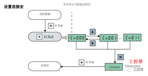
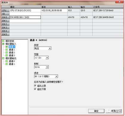
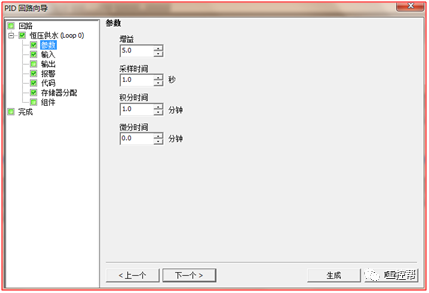
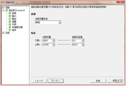
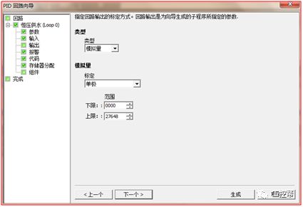
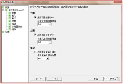
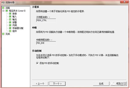
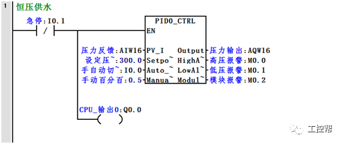
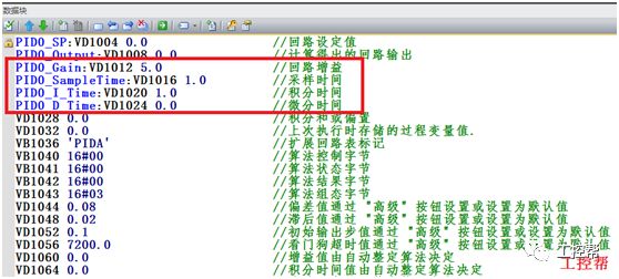
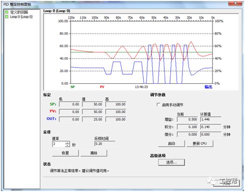
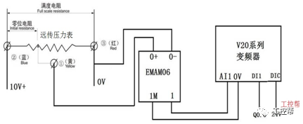
I talked about one of the application modes of PLC control inverter: terminal running command channel + terminal analog channel. The typical application of this mode is to use the remote pressure gauge to detect the pipeline pressure in the constant pressure water supply, convert it into a 0-10V voltage or 4-20MA current analog quantity and feedback it to the PLC, perform PID calculations through the PLC, and then return the calculation results It becomes an analog output, and the frequency of the inverter is controlled through the terminal analog input channel of the inverter to adjust the speed of the water pump, thus forming a closed loop adjustment to achieve constant pressure water supply control, as shown in the following figure: Let's take Siemens V20 inverter as an example to explain how to coordinate control between inverter and PLC. Since the PLC does not have analog input and output functions as standard, an analog input and output module EMAM06 is selected for expansion. The wiring diagram is as follows: 0+, 0- is the analog input interface, 1M, 1 is the analog output interface, DI1 is the V20 digital input terminal, connected to the output point Q0.0 of the PLC to control the start and stop of the inverter, DIC is the common terminal of digital input , Connect the negative pole of the 24V power supply in the picture. So how to set the parameters for the inverter? Before debugging the parameters, restore the factory default value of the inverter, the method is as follows: V20 sets the parameter access level P0003, you need to change the level to expert to access all application parameters, the method is as follows: Set the start-stop command source to external terminal control P0700, the method is as follows: Set the functions of the external input terminals P0701 to P0704, the method is as follows: Set the control line type P0727, the method is as follows: To set the frequency setting and select P1000, the method is as follows: You can also use the macro function to achieve quick debugging. The system provides several commonly used macros, as shown below. Please refer to the V20 manual for the specific parameter settings of each macro. The connection macro method is as follows: Select and connect the corresponding macro. If individual parameters do not meet the control requirements, you can modify them manually. Next, write the control program, first configure the hardware system block, the method is as follows: Then carry on PID wizard configuration, the method is as follows: After writing the program, you can find the addresses of P loop gain, I integration time, and D differentiation time through the wizard data block, and adjust them by modifying the values. The PID parameters need to be set to the power-off hold type. As shown below: It can also be adjusted through the PID panel provided by the software to make the adjustment more intuitive, as shown in the figure below: Self Fusing Rubber Tape,Scotch Self Bonding Electrical Tape,Self Fusing Tape,Rubber Tape Self Fusing Longkou Libo Insulating Material Co.,Ltd. , https://www.sdliboinsulation.com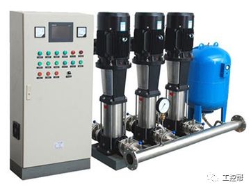
parameter Features Set up P0003 User access level =1 (standard user access level) P0010 Debug parameters =30 (factory setting) P0970 Factory reset =21: Reset the parameters to the factory default settings and clear the user default settings (if stored) P0003 User access level 0 User-defined parameter list 1 Standard: Allow access to commonly used parameters 2 3 Expert: For expert use only 4 Maintenance: only for authorized maintenance personnel, with password protection P0700[0...2] Select command source Select the digital command source. 0 Factory default settings 1 Operation panel (keyboard) 2 Terminal 5 USS/MODBUS on RS485 P0701—P0714 Function of digital input terminal 0 Prohibit digital input 1 ON/OFF1 2 ON reverse/OFF1 3 OFF2-Free stop by inertia 4 OFF3-Quick ramp down stop 5 ON/OFF2 command 9 Fault confirmation 10 Forward jog 11 Reverse jog 12 Reverse 13 MOP (electric potentiometer) speed increase (increased frequency) 14 MOP speed reduction (decrease frequency) 15 Fixed frequency selector bit 0 16 Fixed frequency selector bit 1 17 Fixed frequency selector bit 2 18 Fixed frequency selector bit 3 twenty two Fast stop command source 1 twenty three Fast stop command source 2 twenty four Fast stop overriding 25 DC brake enable 27 PID enable 29 External trip 33 Prohibit additional frequency setting value 99 BICO parameter setting enable Parameter P0727 Features 0 Siemens standard control (start/direction) 1 2-wire control (forward/reverse) 2 3-wire control (forward/reverse) 3 3-wire control (start/direction Parameters P1000 Frequency setting selection 0 No main setpoint 1 MOP setting value 2 Analog setting value 3 Fixed frequency 5 USS/MODBUS on RS485 7 Analog setting value 2 10 No main set value + MOP set value 11 MOP set value + MOP set value 12 Analog setting value + MOP setting value 13 Fixed frequency + MOP setting value 15 USS/MODBUS+MOP setting value on RS485 17 Analog setting value 2+MOP setting value 20 No main set value + analog set value twenty one MOP setting value + analog setting value twenty two Analog setting value + analog setting value twenty three Fixed frequency + analog setting value 25 USS/MODBUS+ analog setting value on RS485 27 Analog setting value 2+analog setting value 30 No main set value + fixed frequency Connection macro description Cn000 Factory default settings. Do not change any parameter settings. Cn001 BOP panel as the only control source Cn002 Control by terminal (PNP/NPN) Cn003 Fixed speed Cn004 Fixed speed in binary mode Cn005 Analog input and fixed frequency Cn006 External button control Cn007 Combination of external button and analog set value Cn008 PID control and analog input reference combination Cn009 PID control and fixed value reference combination Cn010 USS control Cn011 MODBUSRTU control 