1 Introduction GPS (Global Positioning System) was developed for the navigation and positioning of various transportation and mobile equipment at sea, on land and in the air. It has the advantages of high precision, all-weather, global and no need to look through the point, making measurement technology A qualitative leap has taken place. After the introduction of GPS technology into China, especially in the United States after the cancellation of the SA policy, the development has been very rapid in recent years. At present, GPS has been widely used in many fields such as engineering surveying, geographic mapping, transportation and military, and has achieved obvious social and economic benefits, and its development prospects are very broad. This article refers to the address: http:// 2 Terminal hardware design The terminal consists of S3C44B0X and M12 modules and some peripheral devices. The hardware structure of the system is shown in Figure 1. 3 Interface design of S3C44B0X and M12 module The receiving terminal uses the COM0 port of S3C44B0X to issue control commands and receive positioning information to the M12 module. The M12 module supports both the Motorola binary format and the NMEA0183 format. In Motorola binary mode, M12 outputs data and receives instructions at 9600 b/s; in NMEA0183, M12 outputs data and receives instructions at 4800 b/s. By default, the M12 module works in Motorola binary mode. In order to obtain higher data transmission speed, this study uses the default working mode of the M12 module, namely Motorola binary mode. In this mode, the serial data transfer format is: 8-bit data bits, 1-bit stop bit, no parity and hardware flow control. 4 Conclusion This paper describes the design of a GPS data receiving terminal based on the S3C44B0X and M12 modules. It was determined by the static positioning experiment of the GPS reference point (coordinates: east longitude 113°20.538 541', north latitude 23°09.581 834') in the soil tank laboratory of the Engineering College of South China Agricultural University (continued for about 50 min, 3125 groups were collected). The latitude and longitude data, the static positioning data distribution is shown in Figure 5.) The static positioning accuracy of the M12 module is <7.81m, which is in accordance with the accuracy range of <25m under the SA-free policy marked in the user manual. The receiving terminal runs stably, and the positioning information is updated once every 1 s, which can be used as a civil geographic positioning with low precision requirements. A manual pulse generator (MPG) is a device normally associated with computer numerically controlled machinery or other devices involved in positioning. It usually consists of a rotating knob that generates electrical pulses that are sent to an equipment controller. The controller will then move the piece of equipment a predetermined distance for each pulse. Manual Pulse Generator,Handwheel MPG CNC,Electric Pulse Generator,Signal Pulse Generator Jilin Lander Intelligent Technology Co., Ltd , https://www.landerintelligent.com
In the industrial application of GPS, the data receiving terminal is the most basic device. The current data receiving terminal has a trend of increasing intelligence and scalability, which shows that the embedded MCU function is more and more powerful, and the interface is more and more abundant. This paper introduces the design of a GPS data receiving terminal based on the current popular ARM7 architecture-based embedded processor S3C44B0X and Motorola's M12 module.
The S3C44B0X has two fully functional serial ports (UART) with an I/O operating voltage range of 3.0 to 3.6 V. The M12 module provides a serial port for input control information and output positioning and status information. The I/O level is TTL-compliant. The level range is 0 to 3 V. Therefore, the I/O output of the S3C44B0X can be set to 3 V high, and the S3C44B0X and M12 RxD, TxD and GND can be directly connected for asynchronous serial data exchange. Due to the limited internal storage space of the S3C44B0X, an external expansion memory device is required. Here, a piece of FLASH and a piece of SDRAM memory are expanded. In addition, the keyboard and display are attached to the S3C44B0X to provide human-computer interaction. 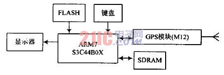
Figure 1 system hardware block diagram
2.1 Interface Design of S3C44B0X and Memory The S3C44B0X does not have a ROM itself. Therefore, an external ROM must be used to store the code and data that need to be saved after power-off. This system uses SST39VF160 flash memory (FLASH Memory) as the ROM of the system. This device is non-easy and easy to erase. The device has a capacity of 1 MB×16, and the interface with the S3C44B0X is shown in Figure 2. 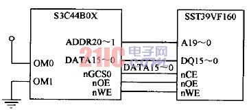
Figure 2 S3C44B0X and SST39VF160 interface diagram Since the terminal uses SST39VF160 as the program memory (including the startup code of the processor), the SST39VF160 is mapped in the Bank0 area of ​​the processor. Therefore, his chip select is connected to the processor's nGCS0.
In order to improve the speed and efficiency of the program, the system also expands SDRAM as the program data temporary storage space. The model of the SDRAM device is IS42S16400. The storage space is organized as 1 MB × 16 × 4 Bank, with a total of 64 Mb, and the data bus width is 16. The interface with the S3C44B0X is shown in Figure 3. 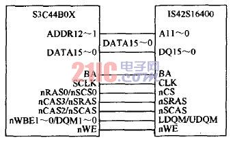
Figure 3 S3C44B0X and IS42S16400 interface diagram
2.2 Interface design of S3C44B0X and LCD This system uses G35_II LCD kit as the display. The screen size of G35_II is 3.5 inches, the resolution is 320×240, and the color is 16 gray. The S3C44B0X contains an LCD driver controller that automatically generates the control signals required for LCD driver control. Therefore, the S3C44B0X can interface directly with LCD screens such as black and white grayscale and STN color without the need for an additional LCD controller. In this interface mode, the LCD display buffer is mapped in the memory space of the system, and the program only needs to write the pixel point content into the corresponding address of the memory to realize the display of the color of the pixel on the corresponding LCD screen. The terminal uses the PC port and PD port of the S3C44B0X as the LCD driver interface, and uses the 4-bit pixel gray mode lookup table and the 8-bit single scan mode for display. The display of the terminal mainly displays the data transmission and reception status and the data flow information.
The S3C44B0X controls it by sending an AT command to M12. According to the Motorola GPS Products-Oncore User's Guide, Motorola has a total of 69 AT I/O commands, of which 51 are supported by the M12 module. With these instructions, it is convenient to perform date time setting, custom coordinate setting and positioning information reading for the M12 module. In the receiving terminal, only the positioning information of the M12 module needs to be read, so only one of the 51 instructions is used in the program:
@@EqmC
This command is used to control the output positioning information of the M12 module. Where "@@" is the prefix of the I/O instruction; "Eq" is the keyword of the instruction; "m" is the M12 module output (response) information mode selection, and its value can be an integer between 0 and 255, when " When m" is 0, the response information is only output once. When "m" is 1, the response information is output once every second. When "m" is 2, the response information is output every 2 s, and so on, when "m" "When 255, the response information is output every 255 s; "C" is the checksum data of the instruction;"
The M12 module can only accept commands entered in Motorola binary form by default. The so-called Motorola binary form refers to the binary instruction code that combines the prefix of the instruction, the keyword and the suffix (carriage return and line feed) into the corresponding ASCII code, and the combination of the mode "m" and the checksum "C". The format of the "@@EqmC" instruction used in this study is as follows:
Message format:@@EqmC
Hexadecimal: 40 40 45 71 00 34 0D 0A
Wherein, the checksum "C" refers to the checksum of "E", "q", and "m", that is, the checksum between 0x45, 0x71, and 0x00 (X045 and 0x71 are XORed by bits) The result is XORed with 0x00 and the result is 0x34. When inputting instructions, only need to follow the 9600 b / s, 8 data bits, 1 stop bit, no parity and hardware flow control serial port format, 0x40, 0x40, 0x45, 0x71, 0x00, 0x34, 0x0D and 0x0A Eight digits are continuously input from the serial port of the M12 module. The M12 module responds within 1 s after receiving its identifiable command.
After receiving and recognizing the command "@@EqmC", the M12 module outputs the positioning information of the following format in the same serial data format and rate when receiving the normal GPS satellite signal:
@@Eq,mm,dd,YY,hh,mm,ss,dd,mm.mmmm,n,ddd,
Mm.mmmm,w,shhhh.h,sss.s,h,m,t,dd.d,nn,rrrr,aa,CC
The information is output in the form of ASCII code, and each piece of information is separated by a comma. According to the explanation of this information by Motorola GPS Products-Oncore User'sGuide, the information can be divided into 7 parts according to the content described. The split format is as follows:
@@Eq,<1>,<2>,<3>,<4>,<5>,<6>,<7>,<8>
Among them, the first part of the information is date information. "mm" means the month, the value is 01~12; "dd" means the day, the value is 01~31; "yy" means the year, the value is 98~18.
The second part of the information is UTC (Universal Coordinated Time) time information. Wherein, when "hh" is a time, the value is 00~23; "mh" is a minute, and the value is 00-59; "s" is a second, and the value is 00-60.
The third part of the information is latitude information. Among them, "dd" is the degree, the value is 00 ~ 90; "mm.mmmm" is the minute, the value is 00.0000 ~ 59.9999; n is the direction, he has two values, one is "N", representing the north latitude, the second is "S" stands for South Latitude.
The fourth part of the information is longitude information. Among them, "ddd" is the degree, the value is 000 ~ 180; "mm.mmmm" is the minute, the value is 00.0000 ~ 59.9999; w is the direction, he has two values, one is "w", representing the West, two It is "E" for the East.
The fifth part of the information is the altitude. Among them, "s" is a symbol, there are two values ​​of "+" and "-"; "hhhh.h" is height data in meters. The range of altitude information ranges from -1000.0 to +18000.0.
The sixth part of the information is speed information. Where "sss.s" is the velocity data in knots, the value is 000.0 ~ 999.9; "hhh.h" is the azimuth data in degrees, the value is 000.0 ~ 359.9.
The seventh part is the status information of the receiving terminal. Wherein, "m" is the positioning working mode information, and the value is 0 or 1, 0 means stand-alone mode (Autonomous), 1 means differential mode (Differentia1); "t" is positioning type information, and the value is 0~3, 0. Represents no positioning, 1 represents 2D positioning, 2 represents 3D positioning, 3 represents broadcast mode; "dd.d" is geometric factor information, the value is 00.0 ~ 99.9; "nn" is the number of satellites in use, the value is 00 ~ 37 "rrrr" is the reference station identification code, the value is 0000 ~ 1023; "aa" is the differential data time in seconds, the value is 00 ~ 60; "CC" is the checksum.
The GPS receiving terminal only needs the M12 module to provide the latitude and longitude position, so the third and fourth parts of the above 7 pieces of information need to be extracted by the program. The COM0 initialization code for the interface between the S3C44B0X and the M12 module is as follows:
UFCON0=0x0;
UMCON0=0x0;
ULCON0=0x3;
UCON0= 0x245;
UBRDIV0= ((int)(Fclk/(16 * 9600))-1);
The interface program flow of S3C44B0X and M12 is shown in Figure 4. The S3C44B0X first requests the M12 module to output positioning data (issue the command "@@EqmC" to the M12 module), and then waits for the M12 module to send back the data. When the M12 module sends back the data, the S3C44B0X first makes a judgment to confirm that it receives the expected positioning information, and then intercepts the positioning information (latitude and longitude data), and arranges the data to display the latitude and longitude data on the LCD after being displayed. Finally, the receiving buffer of the serial port is cleared to avoid an error when receiving the information next time. Since the M12 module can only respond to one instruction within 1 s, the data information of the receiving terminal is updated once every 1 s. 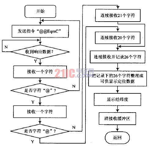
Figure 4 S3C44B0X and M12 interface program flow chart 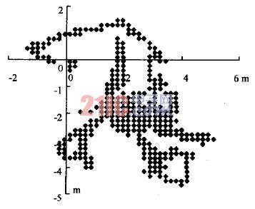
Figure 5 System static positioning value scatter diagram
The CNC handheld controller MPG Pendant with x1, x10, x100 selectable. It is equipped with our popular machined MPG unit, 4,5,6 axis and scale selector, emergency stop and reset button.