Reconfigurable antenna design for handheld mobile terminals Abstract: A design method for reconfigurable antennas that can be used in handheld mobile terminals is proposed. The antenna is equipped with two RF-PIN switches, and the state of the switch can be controlled by a DC control circuit to change the polarization mode and radiation pattern of the antenna, thereby realizing polarization reconfiguration and pattern reconfiguration. The antenna has a compact structure, is easily integrated with a circuit board, and has good application value in a mobile terminal. O Introduction At present, one of the important directions of the development of various communication systems is large capacity, multi-function, ultra-wideband. By increasing system capacity, increasing system functions, and expanding system bandwidth, on the one hand, it can meet the ever-expanding actual demand, and on the other hand, it can also reduce system costs. As the front end of various wireless communication systems, the antenna's performance has an important impact on the overall function of the communication system, so it also puts forward requirements such as multi-frequency, broadband, and miniaturization. With the increasing complexity of wireless communication systems, a single traditional antenna can no longer meet the requirements. Although the multi-antenna design can meet the high requirements of the new generation wireless communication system for the antenna, the increase in the number of antennas will highlight the problems of equipment cost and the spatial layout of the antenna. Especially on handheld mobile devices, due to limited space, the design of multiple antennas is extremely difficult. In this case, the reconfigurable antenna has a very obvious advantage. It can be reconstructed in the antenna pattern, operating frequency, polarization characteristics, etc. without changing the size and structure of the antenna, so that one antenna can realize the function of multiple antennas, adapting to different application environments of mobile terminals And requirements. 1 Antenna structure and design The antenna can be integrated with the circuit board of the handheld device and installed in the upper left corner of the circuit board. Its structure and schematic diagram of the RF-PIN switch control circuit are shown in Figure 1. The usual antenna layout is located on the bottom surface of the dielectric substrate, and the control circuit is located on the top surface of the substrate. D1 and D2 in Figure 1 are two RF-PIN switches; Cl and C2 are bypass capacitors to short-circuit high-frequency signals; L1 , L2 is inductance, open circuit to high frequency signal. The diode and the capacitor are connected to the antenna on the bottom through the through hole. The antenna substrate uses FR4 material with a thickness of 0.8 mm and a dielectric constant of 4.4. The two horizontal and vertical microstrip structures are connected to the circuit board ground through an RF-PIN switch, and the microstrip in the middle is a feeder, and is directly fed through a coaxial cable. The resonant frequency of the microstrip antenna mainly depends on the length of the microstrip line. In general, on a substrate with a dielectric constant of εeff, the waveguide wavelength of the microstrip line is approximately: In Figure 4, Theta represents a horizontally polarized square wave and Phi represents a vertically polarized wave. As can be seen from the figure, on the XY plane, the average gain of the horizontally polarized wave is more than 35 dB higher than the vertically polarized wave, while in YZ On the plane, the horizontally polarized wave has good omnidirectionality, and the average gain is about 10 dB higher than that of the vertically polarized wave, so it can be judged that the energy of the horizontally polarized wave is much greater than the energy of the vertically polarized wave, and the antenna works in the horizontally polarized mode under. 3 Conclusion This paper proposes a design method of a reconfigurable antenna for handheld mobile devices. The antenna is equipped with two RF-PIN switches, which can be controlled by a DC control circuit to make the antenna work. The vertical or horizontal polarization mode also changes the antenna pattern, thereby achieving simultaneous reconstruction of the polarization mode and the pattern. The simulation results show that the -10 dB bandwidth of the antenna can reach 240 MHz in both states. Moreover, by switching the switch state, the antenna can also be switched between the horizontal and vertical linear polarization modes, and the main lobe direction of the antenna radiation pattern can also be deflected by 150 °. The antenna has a compact structure, a small area, is easy to manufacture, and can be used in a multi-antenna system for mobile terminals, so it has good application value in a mobile communication system. Vacuum Cleaner Ac Dry-Wet Motor Vacuum Cleaner Ac Dry-Wet Motor,Vacuum Electric Cleaner Ac Motor,Wet Dry Vacuum Cleaner Motor,Wet And Dry Vacuum Cleaner Motor Zhoushan Chenguang Electric Appliance Co., Ltd. , https://www.vacuum-cleaner-motors.com
Regarding the reconfigurable antenna pattern, the current research mainly focuses on the structure in the form of Yagi. That is, the effective resonance length of the reflector or director is changed by switch control, so as to realize the effect of reflection or guidance and change the radiation direction of the antenna. However, this method requires multiple antennas. Therefore, in the limited space of the handheld terminal, it is very difficult to adopt this method. In addition, in terms of reconfigurable antenna polarization, the focus of research is also on single patch antennas, that is, by slotting the antenna or using multiple feeders, and installing switches at different positions to change the state of the switch to achieve polarization The change of the method, however, this antenna has a large area, and the structure of using multiple feeders at the same time is too complicated to be applied to actual mobile devices.
This paper proposes a reconfigurable antenna for handheld mobile devices. The antenna is equipped with an RF-PIN switch at an appropriate position. The switch can be controlled by a DC control circuit to make the antenna work in two orthogonal linear polarization modes, and also to change the antenna's pattern. Reconstruction of polarization mode and pattern. The antenna has a compact structure, a small area, is easy to manufacture, and has the potential to install multiple antennas on the same terminal to achieve MIMO (multiple input multiple output system), so it has good application value in mobile terminals. 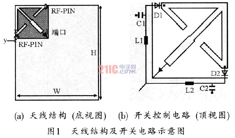

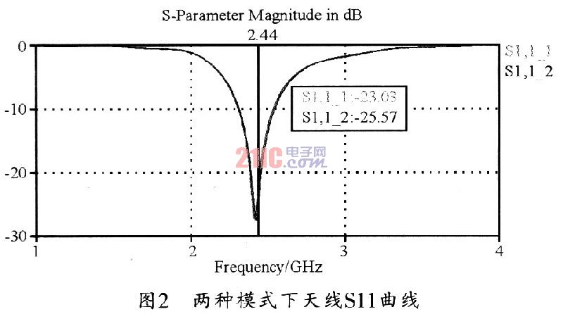
Since the grounding terminal of the antenna is different in the two working states, the effective radiation part of the antenna is also different. When in the X mode, the microstrip line in the vertical part of the antenna structure is grounded. Therefore, the radiating part of the antenna should be a microstrip in the horizontal part, and the antenna also works in the horizontal polarization mode accordingly. Figure 3 shows the RF current distribution of the antenna at 2.44 GHz.
It can be seen from Figure 3 that the RF current is mainly concentrated on the microstrip line in the horizontal direction of the antenna (this confirms the previous analysis). But at the same time, there are also RF currents in the microstrip in the middle part and other parts of the antenna, therefore, the antenna will still radiate some vertically polarized waves. Figure 4 shows the directional diagrams of the two polarized waves of the antenna in the XY and YZ planes. 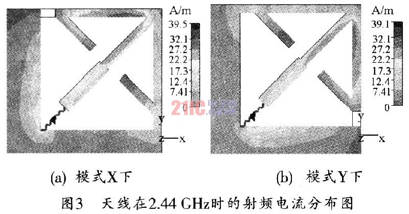
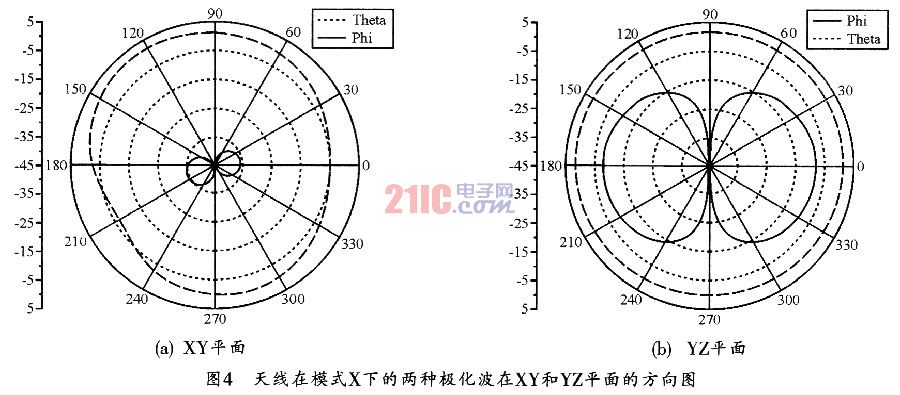
When in the Y mode, the microstrip line in the horizontal part of the antenna structure is grounded. Therefore, the microstrip line in the vertical part is an effective radiator of the antenna. At this time, the antenna also works in the vertical polarization mode. Figure 3 (b) shows the distribution of the RF current of the antenna at 2.4 GHz in mode Y. It can be seen from the figure that the RF current at this time is mainly concentrated on the microstrip line in the vertical direction of the antenna. Work in vertical polarization mode. Figure 5 shows the pattern of the two polarized waves of the antenna in the XY and YZ planes in this mode.
As can be seen from Fig. 5, on the XY plane, the maximum gain of the vertically polarized wave is 37 dBi higher than that of the horizontally polarized wave, and on the YZ plane, the vertically polarized wave also has good omnidirectionality. Its maximum gain is 12 dB higher than the horizontally polarized wave, indicating that in this mode, the antenna can radiate vertically polarized waves well, and the cross-polarized component is very low. 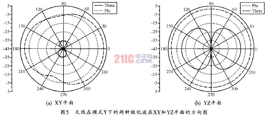
In fact, in both operating modes, the overall pattern of the antenna will change significantly. On the two planes of YZ and XZ. The antenna pattern has good omnidirectionality and can receive incoming signals in all directions as much as possible; on the XY plane, the antenna pattern in the two states is significantly different, the maximum radiation direction will change significantly, and in Good complementarity can be achieved on this radiation plane. Therefore, in practical applications, the antenna state should be changed in real time according to the direction and intensity of the signal wave, and the maximum radiation direction of the pattern should be adjusted to effectively improve the signal-to-noise ratio of the antenna signal, improve the communication rate and system capacity.