The resonant network usually consists of a plurality of passive inductors or capacitors. Due to the difference in the number of components and the connection method, the common and practical resonant converter topologies are roughly divided into two categories: one is load resonance type, and the other is switch. Resonance type. The load resonance type converter is an early proposed structure, focusing on the improvement of the power supply voltage conversion ratio characteristic. According to the resonance mode of the resonant element, it can be divided into a series resonant converter, a parallel resonant converter, and a series-parallel resonance generated by the combination of the two. Converter. Wuxi Motian Signage Co., Ltd , https://www.makesignage.com
Series resonance: due to the series voltage division method, its DC gain is always less than 1, similar to the BUCK converter; to stabilize the output voltage during light load, the switching frequency must be increased. In the case of light or no load, the output voltage is not available. Adjust, the input voltage rises so that the operating frequency of the system will be higher and higher than the resonant frequency, and the resonant frequency increases, the impedance of the resonant cavity also increases, which means that more and more energy is circulating in the resonant cavity without Passed to the secondary output; but in load series resonance, the current flowing through the power device decreases as the load becomes lighter, reducing the on-state losses.
Parallel resonance: the output can be opened but not short-circuited, which will damage the resonant capacitor, and the excessive primary loop current will have an impact on the switching device and the power supply; at light load, it is not necessary to change the output voltage by drastically changing the frequency. The series resonance has a larger working range than the converter, and can work until no load; when the light load is small, the input current does not change much, the on-state loss of the switch tube is relatively fixed, and the efficiency at the light load is relatively low, which is more suitable for the rated operation. Where the load at the power is relatively constant.
Traditional LC series resonant switching power supplies have been forced to increase their operating frequency in order to achieve miniaturization. To reduce the size of the filter inductor and the switching transformer. However, the increase in frequency causes the switching loss to increase and the efficiency to decrease, and the switching noise becomes large.
The LLC series resonant converter mainly uses current resonance. It is a voltage resonance only when the switch is turned from ON to 0FF and OFF to ON. The switching waveform is sinusoidal, so when a voltage is applied to the switching element, a large current does not flow; Moreover, the zero-voltage switching (ZVS) is realized by the parasitic capacitance of the switching element, and the inverter with high frequency, high efficiency, and extremely low noise can be manufactured.
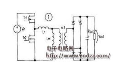
The traditional LC series resonant converter circuit is shown in Figure 1 (without Lm). Lr is the leakage inductance of the switching transformer, Cr is the resonant capacitor, and Tr1 and Tr2 are driven by a 50% N ratio with a small dead time. Since the input-output gain is at most 1 times at the resonance frequency f0 of h and Cr, it is necessary to increase the operating frequency in order to stabilize the output voltage. But in theory. When the load is empty, the frequency must be increased to infinity to stabilize the work. This is a disadvantage of the LC series resonant converter.
Increasing Lm is the LLC series resonant converter circuit. Unlike the LC series resonant converter, a small inductance magnetizing inductance Lm is connected in parallel with the primary side of the switching transformer. The inductance of Lm is only 3-8 times of the leakage inductance Lr; in addition, the core of the transformer has an air gap. To accommodate small magnetizing inductance.
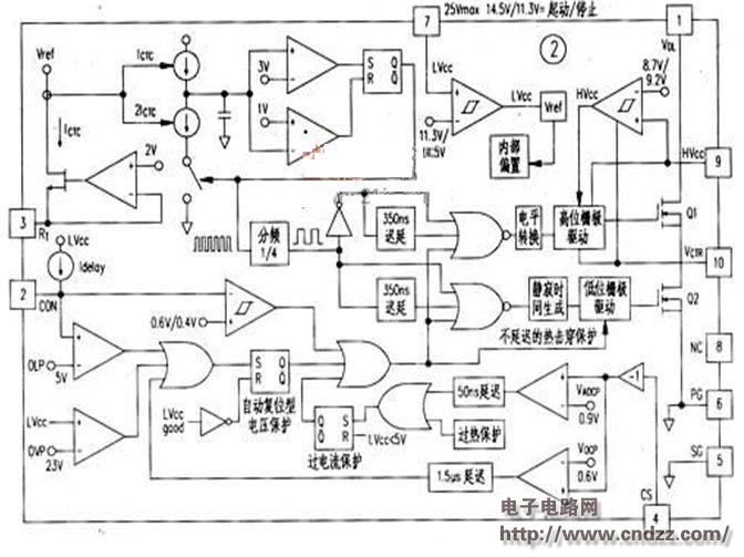
The FSFR2100 is a monolithic LLC series resonant converter IC that includes all the functions of an LLC series resonant converter: VDs = 600V for the internal FET, '32' for the on-resistance, and tn = 120ns for the body diode. â— The silence time is fixed at 350ns. â— Operating frequency is above 300kHz. â— Programmable light load cycle jump operation. â— Remote control ON / OFF with the control terminal (CON). â— Input overvoltage protection. â— Overcurrent protection (detection voltage 0. 6V). â— The thermal shock passes through the current protection circuit (detection voltage is 0.9 V). â— Overheat protection circuit. â— The highest and lowest operating frequency settings. â— Guaranteed frequency control of stable output.
The 1 pin (VDL) of the FSFR 2100 is the internal FET drain voltage terminal; the 2 pin (CON) is the control terminal, 0. 4V or less stops working, 0. 6V or more works normally, and the optocoupler is connected to realize the cycle skip operation; The 3-pin (RT) is the frequency control terminal and is controlled by the optocoupler constant voltage. And the highest and lowest frequency and soft start settings; 4 feet (CS) is the overcurrent detection terminal, 0. 6V action, 0. 9V heat shock through the flow protection action, need to connect CR filter; 5 feet (SG) For the signal ground, connect the PG terminal to the ground of the control circuit; 6 pin (PG) is the power supply ground, the source of the low FET; 7 pin (LVcc) is the control circuit power supply terminal, 25 Vmax, the startup voltage 14. 5Vtyp Stop voltage 11.3Vtyp; 8 pin (NC) is empty; 9 pin (HVcc) is high FET drive power, usually LVcc: supplied by charge pump, ground voltage 625Vmax; 10 pin (VCTR) is high, low FET Connection point. 

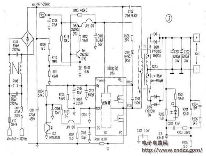
Figure 2 shows the internal block diagram of the IC and Figure 3 shows the application circuit. The input voltage is D (B40V-400V: output capacity 24V / 8A, 192W: T1 primary coil 36 åŒ. Inductance 630 μ (including excitation inductance 4951xH and leakage inductance 135 μ H); two secondary coils each 4 åŒ; resonance Capacitance 22nF. 