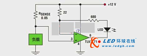
The LED's luminous intensity is proportional to the load current. The circuit is designed to provide a very compact circuit to replace the meter on the 12V power line in some astronomical equipment. This device contains low power heating elements (anti-dew elements) that are not visible in the working condition. However, when the heater is turned on, the LEDs emit a visible light that clearly indicates that they are connected and working. Circuit analysis is very simple. The voltage across the 22 ohm resistor is the same as the voltage across RSENSE. The current flowing through the 22 ohm resistor is the same as the current flowing through the LED. Therefore, for the parameter values ​​given in the figure, the LED current is equal to 0.05/22 of the load current. When the load current changes from 200 mA to 6.6 A, the LED changes from weak illumination to full brightness (limited to 680 ohm resistance). If necessary, add another LED with a fixed resistor for comparison. In addition, the histogram display results can be obtained by constructing different examples of the circuit. In these circuit examples, the resistors of 22 ohms are replaced by different resistors, and RSENSE remains unchanged. The op amp must have an input and output that can reach the positive rail and can withstand a supply voltage slightly above 12V. TI's TLV2731 is ideal for meeting these requirements. When the load current is 200mA, the LED emits weak light; when the load current increases to 6.6A, the LED emits the brightest light. Interior Lighting,Ambient Indoor Lighting,Commercial Lights Indoor,Indoor Lighting t-smartlight , https://www.t-smartlight.com