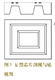
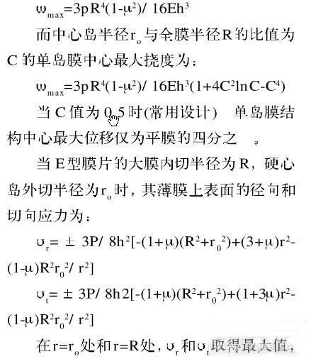
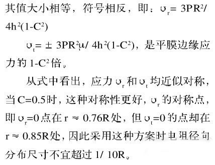
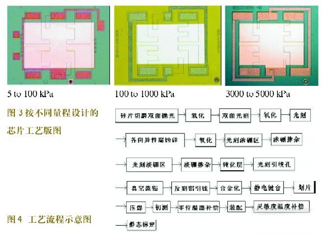
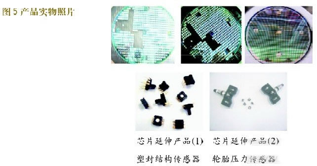
During high-speed driving, tire failure is the most worrying and difficult to prevent for the driver, and it is also an important cause of sudden traffic accidents. According to a survey by the Society of Automotive Engineers, 260,000 traffic accidents per year in the United States are caused by low tire pressure or leakage. In addition, 75% of tire failures per year are caused by tire leakage or insufficient inflation. According to experts from the National Rubber Tire Quality Supervision Center, 70% of traffic accidents on Chinese highways are caused by punctures, while in the United States, this proportion is as high as 80%. How to keep tire pressure in harsh working conditions In the environment, it is possible to drive normally and discover the leak of the tire in time, which is the key to preventing the tire from puncture and safe driving. Therefore, the tire pressure detection during travel is particularly important. Nowadays, many national highway safety associations have enacted legislation. The tire pressure monitoring system TPMS (Trie pressure monitoring system) has a significant impact on improving vehicle safety, while its low-power, long-term reliability in harsh environments Smaller pressure sensor error tolerance and longer working life are the key requirements of TPMS, so the design and chip selection of the solution also surround these requirements. This article refers to the address: http:// At present, there are three main implementations of TPMS, namely direct TPMS system, indirect TPMS system and hybrid TPMS being introduced. However, indirect TPMS has certain limitations. The direct TPMS directly measures the air pressure of each tire using a pressure sensor fixed in each wheel. These sensors then send the tire pressure data to the central microprocessor for analysis via the transmitter, and the results of the analysis are transmitted to the display mounted in the vehicle. The type of display differs from the simple tire pressure indicator assembled on most vehicles today, which shows the actual air pressure of each tire and even the air pressure of the spare tire. Therefore, directly including the slave task, the TPMS can be connected to the display. Tell the driver which tire is under-inflated and can detect a small air pressure drop. To meet the multi-tire pressure sensing requirements, hybrid TPMS can overcome the limitations of conventional direct TPMS due to the installation of direct air pressure sensors, which are capable of detecting two tires in a low pressure state on the same axle or on the same side of the vehicle. The system can also detect faults when all four tires are in low pressure. The target product of automotive tire pressure sensor IC chip is the vehicle tire pressure monitoring system TPMS which combines MEMS technology and integrated circuit technology. This paper focuses on the design, processing and production of tire pressure sensor IC chips using MEMS micromachining technology. That is, through the micro-machining process, the tire pressure sensor IC chip with low cost parameters and performance can compete with similar foreign products. For the domestic TPMS manufacturers supporting, and gradually superior cost performance for the international manufacturers to provide chips. Structural principle The chip design uses a single island film structure. The following figure shows a cross-sectional and bottom view of the single island film structure of the product (also known as the E-type silicon cup structure). The diaphragm-like structure (commonly known as the C-type structure) equivalent to a peripherally fixed flat membrane has a thick hard island. Through calculation and experiment, the chip's anti-overload and anti-vibration ability, while also expanding and increasing the range of varieties and extending the service life, the principle structure of the E-type silicon cup is shown in Figure 1,2. In the product technology design, the versatility of the sensor parameter index is taken into account, and the chip application is extended to the manifold pressure sensor of the automobile engine EFI system. Avoid non-professional matching of its parameters, such as high temperature coefficient, low overload capability, and dispersion of sensitivity parameters; the substrate concentration of the chip is much larger than 103, which makes the bridge resistance high, reduces power consumption, and prolongs the use of power supply batteries. life. According to the design calculation, the chip layout design E-type silicon cup structure is 2.4×2.4mm, the large film radius R is 0.8mm, the central island radius ro is 0.4mm, the resistance strip width is 4mm, the length is 80mm, and the design is 20 Square resistance, the shape of the resistor is a single strip shape. To reduce the influence and error of the tip, the resistor is formed by doping with light boron, the square resistance is 250 ohms, the terminal is short-circuited with concentrated boron, and the square resistance is 10 ohms. Considering layout techniques such as the effect of the alignment of the additional resistance on the balance of the concentrated boron on the bridge. Mathematical model and analysis The maximum deflection of the center of the flat diaphragm with radius R is: Implementing process points Process layout design When the chip size is increased and thickened, the chip scale can be expanded. The chip is a square flat diaphragm with a fixed edge and has a load capacity of 3 to 10 times. Figure 3 shows the chip process layout designed according to different ranges. The main technical problems solved: 1 high quality silicon-silicon vacuum bonding process; 2 uniform and high pass rate thinning process; 3 high accuracy and high uniform doping consistency and slender resistance bar consistency control to ensure low temperature drift of the sensor; 4 internal stress matching elimination technology to ensure the time stability of the sensor; 5 corresponding anti-electromagnetic interference design; 6 measures for high vibration and centrifugal acceleration in package design and process; The process flow diagram is shown in Figure 4. Indicator test The products of this project are based on the international standard of automobile tire pressure, combined with the product use requirements put forward by domestic users, according to the relevant product standards reviewed by the Electronic Standardization Institute and the Beijing Municipal Bureau of Technical Supervision, after the type test of the Space Department 304, the performance is tested. The indicators are in line with the design usage indicators. Application development and extension Combining the characteristics of MEMS technology, taking into account the generality of the post-package production process equipment, in the design of the chip structure, considering the structure and parameter requirements of the chip to meet different products, according to the minimum requirements and classification principles of chip size and process layout, structural design Divided into three chip types, the chip variety has been greatly reduced, and the application field of the chip has been expanded. Conclusion The use of MEMS technology to produce automotive tire pressure sensors, with small size, low energy consumption, stable performance, is conducive to mass production, reduce production costs, and increase product added value. At the same time, it broadens the scope of application of the product, and increases the value of chip promotion and the economic benefits of the product. The development of automobile tire pressure sensor chip is to reduce the sudden and serious traffic accidents caused by the puncture of high-speed cars, ensure the safe and smooth highway, avoid personal injury and family tragedy, and the long-term stability of the entire national society and the entire national. Economic development has important social and practical significance. Figure 5 Product photo
IDC (insulation displacement contact) D-sub connectors are a type of electrical connectorthat's designed to be connected to the conductor(s) of an insulated cable, most commonly a ribbon cable(a cable with many conducting wires running parallel to each other on the same flat plane).
Applications for IDC D-sub connectors
IDC D-sub connectors, attached to ribbon cables, are helpful in situations where you need to make a lot of connections without a big number of wires. They're commonly used in computer and electronic systems that require multiple data buses to link internal peripherals, such as disk drives to their drive controllers. They're also frequently used in industrial and telecom applications.
How does an IDC D-sub connector work?
With an IDC D-sub connector, there's no need for cable preparation – in other words, you don't need the strip the cables of their insulation before connecting. To connect the cable to the connector, there are sharpened blades (or contacts) on the connector that force through the insulation around the cable, making a secure connection.
IDC D sub connector from Antenk, Outstanding features high contact reliability, long life and low contact resistance.
IDC D-Sub Connectors Low Profile IDC D-Sub Connectors,Flat Cable IDC D-Sub Connectors,D Sub Connector IDC Type,IDC D-Sub Standard Connectors ShenZhen Antenk Electronics Co,Ltd , https://www.antenk.com