Simulation Design of Radar System Based on Matlab
0 Preface
In recent years, some radar simulation systems have been developed internationally, and the research of domestic phased array radar systems and pulse compression radar system simulation software has become a hot spot. For a complex radar system, system modeling and simulation technology is an important direction and development trend of radar system design and research. These simulation software systems are mainly for engineering designers and have high practical reference value. Based on this, this paper refers to the simulation ideas of the radar system mentioned above, and uses Matlab graphical user interface to develop a set of radar system analysis auxiliary teaching software package for student self-study and teacher teaching. The software package is mainly based on teaching self-learning auxiliary software, for learners to efficiently understand and master the relevant knowledge of radar system analysis.
In all kinds of teaching experiment software, it is often limited to Matlab programming, but there are still deficiencies in close to the needs of learners and multimedia learning. Matlab has very powerful functions such as numerical calculation and data analysis and processing. However, the Matlab program is an interpreted and executed program that does not require pre-processing such as compilation, which causes the program to run slower. VC has high coding efficiency, and can directly operate the operating system, application programs and hardware. Therefore, this software package uses mixed programming of Matlab and VC, which improves the efficiency of the code and takes advantage of the two languages. The running result shows that the software package has good human-computer interaction function, high software running speed and rich multimedia learning methods.
1 Use VC and Matlab mixed programming to achieve MEX file
In the mixed programming of Matlab and VC, they can be divided into two aspects: calling VC program in Matlab and calling Matlab in VC. The former aims to make up for the software functions that Matlab program cannot realize or solve the defects of Matlab running speed is slow; the latter is generally to call Matlab program in VC environment, and make full use of Matlab's powerful advantages in matrix calculation and data analysis.
Before Matlab and VC mixed programming, we must first set the correct settings for Matlab's compiled application max and compiler mbuild. Set up the MEX compiler and generate a configuration file that is a batch file with the suffix bat. It is achieved by entering the command: mex-setup in the Matlab command window, and then selecting the compiler and path according to the output information prompt. There are two main ways for Ma-tlab to call VC: using MEX technology and VC dynamic link library. This article writes the mexrun file by calling the VC dynamic link library. In fact, you can easily edit MEX files in the Matlab environment, but for large MEX programs, it may be more complicated and error-prone, and you can use the powerful debugging functions of Visual C ++. Figure 1 shows the process of creating a MEX file in a VC environment.
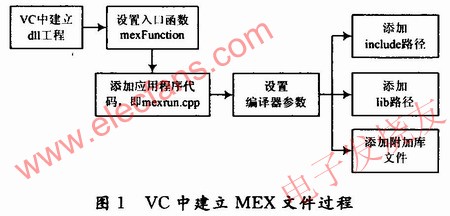
Matlab provides an interface to the DLL file of the dynamic link library, and its interface supports the DLL file written by VC, so after compiling the m file, a mexrun.dll dynamic link library file with the same name as mexrun.cpp will be generated. In this way, you can directly call back the mexrun () function in the m file of Matlab. The mexrun file is written through VC because files such as MP3, MP4, CHM and TXT need to be run directly in Matlab, and the implementation efficiency of this process using Matlab itself is low, and the code is repeatable. The format also needs to be treated differently. Therefore, considering the direct connection between the VC language and the operating system and hardware, writing programs through VC and providing them for Matlab call will undoubtedly improve the operating efficiency.
The following header files need to be included in the mexrun.cpp file:

The C language MEX file source program is mainly composed of two parts: the first part is the algorithm program, used to complete the actual work; the other part is the entry subroutine, which is the interface between the algorithm program and Matl-ab. The entry subroutine realizes the interface function by obtaining the data required by the algorithm program in the input pointer array, and at the same time can also return the calculation result to the output pointer array. Here mexFuncTIon has the function of input / output and variable conversion. Refer to the mexrun.cpp file written in this article, you need to pay attention to the following points:
(1) void mexFuncTIon (int nlhs, mxArray * plhs [], int nrhs, const mxArray * prhs []). Nlhs in the function header is the number of output parameters in the Matlab command line mode; * plhs [] is a pointer array of mxArray structure type pointing to all output parameters; * prhs [] is also a mxArray structure type pointing to all input parameters Pointer array; nrhs is the number of input parameters.
(2) The following variables need to be defined: char * input_arg1, * input_arg2; int len1, len2, status1, status2. Among them: * input_arg1, * input_arg2 are two character pointers; len1, len2 represent the length of allocated space; status1, status2 are two data space variables.
(3) The input must be a single-line character string, line vector, as follows:

(4) Copy the input string into the C string, as shown below:
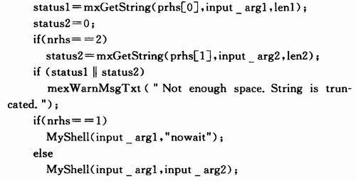
After setting the compilation environment and source program according to the above procedure, you can compile this project. After the compilation is successful, the mexrun.dll link library file will be generated in the debug folder. The experimental results show that as long as the mexrun.dll link library file is placed in the current working area of ​​Matlab, it can be directly called in the m file writing in GUI design.
2 Design and implementation of system modules
The overall structure of the radar system software package adopts a separate multi-module structure, that is, each functional module is independent of each other and performs certain functions respectively. From the perspective of user convenience, the designed radar system software package uses a multi-level hierarchical menu-driven form. The main menu first selects the sub-menus of each functional module. Under each menu of the functional module, you can choose parameter settings and programs Run, get help, and return to the previous menu.
2.1 System implementation method
A graphical user interface (GUI) is a way for users and computers to communicate information. The computer displays graphics and text on the screen, and the user communicates with the computer through input devices such as a keyboard and a mouse. The GUI contains various controls. By setting some event response functions to the controls, these functions can be executed when events such as the creation or deletion of controls occur, so as to realize certain functions that are triggered by specific events. These event response functions are the callback functions of the handle graphic object.
This article uses the GUIDE interface to lay out various controls, and uses the property editor to set each control. The experiment interface of the software package mainly includes login interface, main interface and various sub-interfaces. The following uses the login interface as an example to illustrate the design process of the graphical user interface.
2.2 Login interface settings
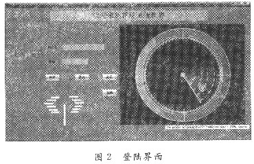
Figure 2 shows the setting of the login interface under the GUIDE interface, which includes buttons, static text boxes, edit boxes and coordinate axes. When editing the attribute editor of each control, Matlab initializes a callback function in its corresponding m file for each control.
First, you can open the help document, MP3 file, and MP4 file by calling the mexrun.dll library file implemented by mixed programming. Take the video button as an example, open its property editor to see its corresponding Tag property pushbuttonl, and add the following code to its callback function. After the video button opens, it is a simple video about the instructions of the software package.

Second, write the properties and constructor of the coordinate axis control. The coordinate axis function here is used to display a static image in JPEG format. Matlab provides imread () function and imshow () function to read and store static pictures. X in the function is a matrix.

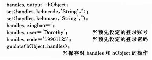
Finally, regarding the password setting of the login interface, you need to initialize the () pening Fcn function, which is the default user account and password of the software package. Here you need to use the function set () to set the string entered in the edit box, that is, the user account and password, and initialize the account and password.
3 Simulation results
The analysis of the radar system includes the analysis of the simulation results of various parts. Here, the typical linear antenna array simulation results in the radar antenna are selected for analysis. An example of the simulation interface is shown in Figure 3. The example selected here is the gain pattern of the linear antenna array. Among them, the number of elements in the array is 19, and it can be seen that when the distance between the elements is 1.5 wavelengths, the scan angle is -38 °, the Ham-ming window is used for amplitude weighting, and the 23 quantization level is used, the corresponding value is -38 ° There is a main lobe, and the level of the first side lobe is about -13.4 dB. If you select different settings in the panel, you can get the gain direction for different array antennas (that is, different number of elements in the array or different element spacing), different scanning angles, different windowing functions, and different quantization levels Figure.
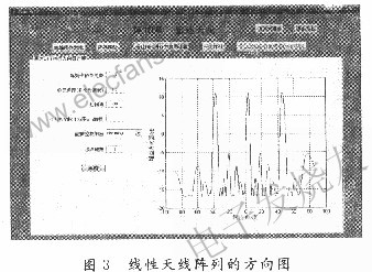
Through the system simulation and comparison of the simulation results, you can clearly understand how the antenna's gain direction at each steering angle changes with the parameters of the antenna array's cell spacing, scanning angle, windowing function, and quantization level. And it changes, so as to form an intuitive experience of the gain pattern of the linear array antenna.
4 Conclusion
The radar system analysis course is highly theoretical and difficult to understand. How to help learners understand the basic concepts and basic analysis methods in the course is the key problem to be solved in the course teaching. Considering that Matlab's graphical user interface is very vivid, this article uses VC and Matlab mixed programming to fully develop the advantages of the two languages, and develops and implements the GUI teaching software package for the course teaching experiment. Experiments show that the radar system simulation software package has a friendly interface, flexible parameter setting, and can see text or graphic descriptions of radar signal transmission, reception and signal processing at any time during the simulation process.
Welcome to reprint, this article comes from the electronic enthusiast network (http: //)Floating Board To Board Connector
FLOATING Board to Board Connector
FLOATING Board-to-board (BTB) connectors as the name indicates is used for connecting circuits board together. This kind of connectors are suitable for stacking circuits boards one over another. Flat flexible cables can be avoided using these kinds of connectors; moreover it makes the entire unit more compact. The commonly used BTB connectors are SMT connectors and Berg Strip. We will discuss about them in detail in the following section.
SMT CONNECTOR
Surface Mount Technology (SMT) connector is a commonly found board-to-board connector in advanced circuit boards. As the name indicates this connector is available only in surface mount model. It is carefully mounted on to the solder pads on the surface of the PCB.
SMT connectors are ideal candidate for miniaturization due to their small area of occupancy and stacking height. They are suitable for double layered or multilayered PCBs. They are designed for high performance and reliability.
They commonly found in advanced circuit boards in networking equipment, telephones, mobile phones, computers and other consumer electronics.
Floating Board to Board Connector
ShenZhen Antenk Electronics Co,Ltd , https://www.antenksocket.com