Various motors (including linear motors), from the perspective of the magnetic field, can be regarded as the result of the interaction between the stator magnetic field and the rotor magnetic field, and the two magnetic fields remain relatively static, but their working angle (the angle between the two magnetic fields) Different. DC motor: The stator magnetic field is a fixed magnetic field, and the rotor magnetic field and the stator magnetic field are perpendicular to each other, and the relative position of the space is kept unchanged. Asynchronous motor: The stator magnetic field is a rotating magnetic field. The conductor in the rotor cuts the rotating magnetic field of the stator, generates an induced current, and forms an induced magnetic field in the rotor. The magnetic field follows the stator magnetic field synchronously, and the angle between the two magnetic fields is approximately 90 o . Synchronous motor: The stator magnetic field is a rotating magnetic field, the rotor armature is excited by DC to a fixed magnetic field, and the stator magnetic field rotates synchronously with the rotor magnetic field to form an angle of 0 o . Stepper motors, whether reactive or hybrid, are nothing more than a synchronous motor with no external excitation current. After the stator magnetic field is excited, the rotor magnetic field runs synchronously with the stator magnetic field and remains relatively stationary at the position of the space, that is, the angle is 0 o , that is, in the state of minimum reluctance. When the "synchronization angle difference" between the rotor and the stator is greater than half of the step angle, then "out of step" occurs. The stator magnetic field excitation method of the stepping motor is different from the number of phases of the motor winding, and even if it is the same motor, there are different ways, and thus many driving circuits are generated. But in summary, these conventional lines, which are designed to operate the stepper motor in a "stepping" manner, have a "stepping" pulsating rotating magnetic field in the stator of the stepper motor. They use the operating characteristics of stepping motors to varying degrees, such as low-speed oscillation, low-speed torque, resonance, out-of-step, low resolution, and high power consumption, so that the servomotors for stepper motors cannot be achieved and satisfied. High precision and high speed requirements. For these shortcomings of stepping motor, a new driving concept-synchronous vector operation mode of stepping motor is proposed, and the synchronous vector servo system of SV series stepping motor is successfully developed. 1 system computer theory based on the above characteristics of the stepper motor in the principle of magnetic field action, it is envisaged that a uniform continuous rotating magnetic field with constant mode field strength is generated in the stator of the stepping motor, so that the stepping motor is synchronously smoothed under the action of the field. Ground operation. Taking the three-phase stepping motor as an example, the principle is briefly described. A uniform circumferential rotating magnetic field to be formed in the stator of the stepping motor, as shown in FIG. Let P point be any point on the unit circle, the vector å‡åŒ€ rotates evenly along the circumference, and the mode lOPl is equal to the constant; for this purpose, a mathematical model is to be established, so that the excitation current flowing in the three-phase winding is generated at any angle. Required synthetic magnetic field vector
Not only fashionable, but also protective. Our protective sleeves provide impact protection, shock absorption and a slim design. The Phone Case can give you peace of mind and provide better protection. If you keep your phone clean and scratch-free, you can also increase the resale value of your phone.
Design: The fit design makes your phone slimmer.
Protection: These Mobile Phone Case have been tested to withstand those accidental drops. The inner layer is made of Soft TPU rubber material, and the reinforced corners can absorb impact. High lips recess your screen and camera to provide additional protection. The outer hard shell is impact resistant.
Function: When all ports can be accessed, your phone can be used normally. The Cell Phone Case has molds for volume buttons and power buttons, so it is protected and you can still feel/use them.
If you want to know more about Mobile Phone Case products, please click the product details to view the parameters, models, pictures, prices and other information about Mobile Phone Case.
Whether you are a group or an individual, we will try our best to provide you with accurate and comprehensive information about the Mobile Phone Case!
Matte Phone Case, Marble Phone Case, Protective Case, Iphone Case, Transparent Phone Case, Protective Cover Shenzhen Jianjiantong Technology Co., Ltd. , https://www.jjthydrogelmachine.com
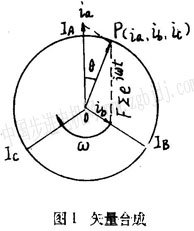 The following equation can be obtained from Figure 1.
 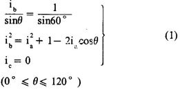 Organize and solve the equation
 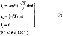 The same reason
 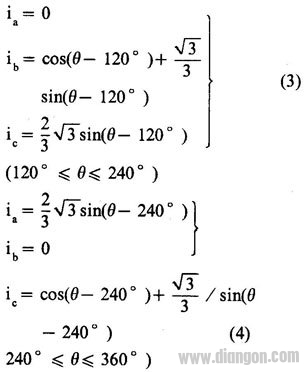 Of course, these can also be obtained by the theory of electromagnetic fields, and the results are the same. They are a set of bimodal curve functions with a phase difference of 120 o , and their waveforms are shown in Figure 2.
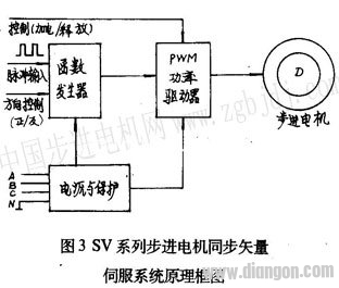
 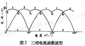 It can be seen from Fig. 2 that when the three-phase stepping motor works in any one of the stepping modes of single three-shot, double three-shot, three-six-six, etc., the phase current value is only a special point on the current waveform. As shown in Figure 2, Pl, P2, P3, P4. They are located at 0 o , 60 o , 120 o , 180 o , 240 o circumferential angles in one cycle, and their amplitude is equal to one unit, that is, the rated value of the phase current of the stepping motor when running in step mode. At the same time, it can be seen that each cycle of the phase current is equivalent to six steps of the three-six-six system or three steps of the single-three-shot system when the stepping motor is operated in the stepping mode. In other words, such as the BF11 type stepping motor. The above bimodal curve can be rotated once every 80 cycles. 2 SV series stepping motor synchronous vector servo system SV series stepping motor synchronous vector servo system is one of the typical lines to realize the above principle. The system consists of function generator, power driver, power supply and protection circuit. The system block diagram is as follows. Figure 3 shows.
  2.l function generator In order to achieve direct digital control, the resulting phase current function is required to be discrete. If it is discretized in the above formula
 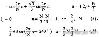 Where N is the number of composite vector points divided by a discrete function period, which is determined by the actual required resolution; n is the number of random input pulses, N and n are positive integers. The function generator that implements the function discrete expression consists of an N-ary reversible counter. ROM and D / A converter and other components, the principle shown in Figure 4.
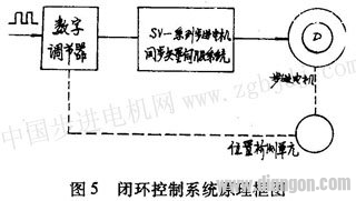
 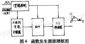 The discrete function value is solidified in the ROM, the input pulse changes the state of the counter, the ROM is addressed, and the corresponding data taken from the ROM is reproduced by the D/A converter to the function value, which is provided for the lower power driver. Phase current function bimodal curve signal. 2.2 Power Driver The power output stage uses advanced PWM technology to output the bimodal curve current and directly drive the stepper motor winding. 2.3 Power supply and protection circuit For small stepper motors and power stepping motors with low speed range, generally use fixed voltage to directly supply the drive stage; for large and medium-sized power stepper motors and wide range of speed requirements In the case of use, a variable voltage power supply (using fv variable frequency transformer technology) is used to improve the moment-frequency characteristics of the system, and reduce the power consumption of the output driver stage to reduce the heating phenomenon. The protection circuit adopts high-speed electronic automatic protection technology, which will not cause fatal damage to the system in the event of overvoltage, short circuit or overcurrent. Taking BFl10 stepping motor as an example, the relationship between IV selection, feed pulse, control precision and resolution in SV series stepping motor synchronous vector servo system is illustrated. In order to balance most common drive screws directly connected to the stepping motor (such as pitch 2, 3, 4, 6, 8, 12mm, etc.), the SV series servo system generally takes N=90, therefore, the stepper motor stator The number of equal-strength synthetic magnetic field vector points is equal to 90x 80=7200. If the transmission mechanism connected to the stepping motor is 6mm per revolution, then every 12 pulses are displaced by 10μ/m during open-loop control. A certain number of pulse trains are equivalent units between the feed pulse and the control displacement, which is not a "one-to-one" relationship of the stepwise mode, which is especially important for forming a closed-loop control system. The stepping motor winding is excited by the phase current of the bimodal curve, and the leading edge rises smoothly, which overcomes the transition process caused by the sudden change of the phase current when the winding inductance acts on the conventional pulse driving line, effectively suppressing the stepping. Oscillation during motor operation and resonance during acceleration. At high speeds, the phase current is approximately rectangular, thus greatly improving the high speed moment frequency characteristics of the stepper motor. The speed of the stepping motor is proportional to the input pulse frequency. When the input pulse frequency is 120Hz, the stepping motor speed is lr/min; the measured no-load maximum speed exceeds 3000r/min. At this time, the input pulse frequency is set according to a certain law. When changing, the stepper motor rotor also operates at speed up, down speed, and constant speed. By changing the counting direction of the reversible counter, the direction of rotation of the stepping motor can be changed. That is to say, when the DC servo system controls the DC servo motor to reverse from 0 to the maximum speed with O~±10V input voltage, the SV series stepping motor synchronous vector servo system changes from 0 to the input pulse frequency. To control the speed of the stepper motor. The step response of the system, the external characteristic hardness, etc. can be similar to the same power DC servo system. The system uses TTL-digital circuit levels to interface directly with the computer. Increasing the number of equal-point points of the stator constant-mode synthetic magnetic field of the stepping motor can improve the resolution and control accuracy of the stepping motor. For example, in a factory in Zhengzhou, BFll0 type three-phase stepping motor, taking N is 125, (previously used N=250), the number of synthetic vector points of the stepper motor stator is 125×80=10000, on the machine tool. Directly connected with the 5mm ball screw, the group pulse equivalent is two pulses per 1/μm. After repeated practical measurement, the open-loop control accuracy is ±2μm, the repeat positioning accuracy is ±1μm, and the machined surface roughness is R a O. 04μm, the high precision requirements of the machining process are achieved. Of course, the control accuracy is further improved, and a closed loop system must be used. The principle block diagram is shown in Fig. 5.
  If the internal winding of the stepping motor is changed to a three-phase AC motor, it becomes a three-phase AC stepping motor with a concentrated winding. At this time, the phase current of the uniform circumferential rotating magnetic field generated in the stator is known as the three-phase sinusoidal alternating current. The maximum amplitude can be reduced to half of the rated phase current of the stepper motor. 3 Conclusion In theory, the stepper motor stator can be “infinitely†halved by establishing a constant-mode synthetic magnetic field vector to arbitrarily improve the resolution of the stepping motor, but due to the nonlinearity of the magnetic material and the structure of the stepping motor itself. As well as various aspects of the process technology, in fact, the synthetic magnetic field generated by the stator of the stepping motor under the phase current excitation is not absolutely uniform. In a functional period, the angular difference of the stator magnetic field formed by any two adjacent pulses is different from the theoretical uniformity when the rate of change of the phase current function is large and small, thus affecting the stepping motor. The uniformity of the rotor's micro-rotation angle (but the simultaneous deviation of each function is basically the same). These can be started from the correction function on the one hand, and on the other hand, it is hoped that the stepper motor manufacturer can improve the uniformity. The stepper motor driven by the function current has lost its original "stepping" meaning, and the motor itself is only used as a servo motor in this system. Manufacturers should try to increase the torque and magnetic saturation margin of the same volume of motor in order to develop a most complete adaptive drive system.