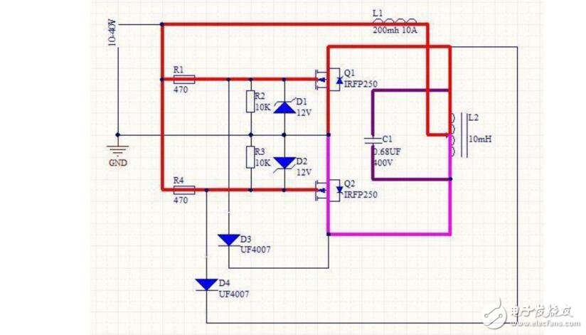
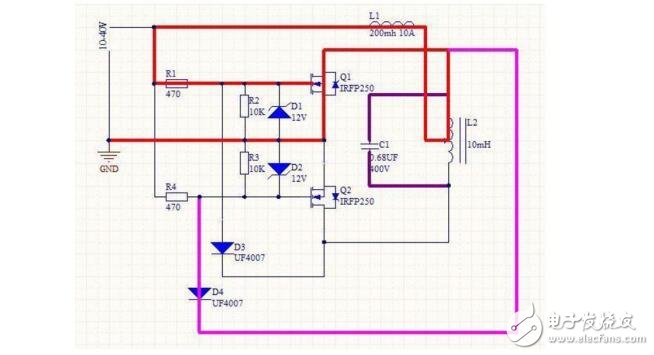
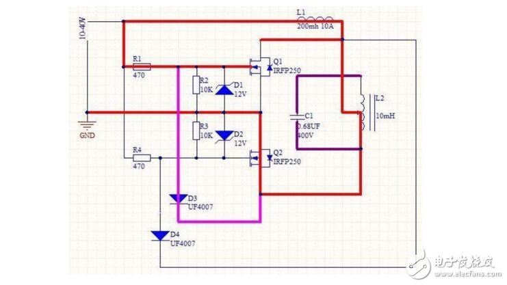
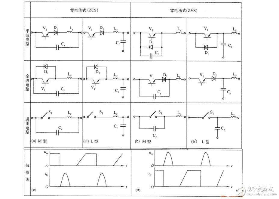
The PWM switching power supply works in hard switching mode (the voltage drop/rise and current rise/fall waveforms overlap during the on/off process), so the switching loss is large. Although high frequency can reduce the volume and weight, the switching loss is even greater. For this reason, it is necessary to study the technology of switching voltage/current waveforms that do not overlap, that is, the so-called zero voltage switching (ZVS)/zero current switching (ZCS) technology, or soft switching technology. The efficiency of small power soft switching power supplies can be increased to 80%. ~85%. The principle of zero-voltage switching is nothing more than the same as an ordinary transformer, a core heating, or a simple induction cooker. An alternating magnetic field is applied to the coil. When you put the iron rod into the coil, the iron rod generates an induced current, and then heats up and burns red. The figure is a typical zvs circuit diagram. Many people make it according to the picture. As long as the wiring is correct and the components are selected reasonably, the production can be successful, but do you know how this circuit works? Let me give you a detailed analysis. Look at the picture first: We know that there will be slight differences between two components of exactly the same model as the electronic components such as transistors, resistors and capacitors. During the initial power-on period, Q1 and Q2 will always turn on first and then turn on. Assuming that Q1 is turned on first and Q2 is turned on during the power-on period, as shown in the figure above, we can see that the current flows to the negative pole of the power supply through L1, L2 and Q1, and the current flows through L1 L2 Q2 flows to the negative pole of the power supply. At this time, the capacitor C1 is charged. Many people feel that this has been the same. How can the alternating magnetic field be generated? We then look at the picture below: When Q1 is turned on, the cathode of the D4 fast recovery diode is equivalent to being grounded by Q1, and the diode is forward-conducting, which makes the originally conductive Q2G electrode grounded, and then Q2 is turned off and does not conduct. At this time, our C1 is on the stage. Because C1 is charged during the power-on period, and because C1 is connected in parallel with L2, C1 discharges to L2. Since the inductor current cannot change suddenly, when the charge of C1 is about to be discharged, L2 turns to C1 charges and forms resonance. While C1 discharges to L2, the S pole of the upper tube is also charged, Q1 then turns on, D4 turns off, and Q2 turns on. The result of Q2 turning on is to pull down the cathode of D3, and D3 turning on turns the on of Q1 off. This circuit keeps running like you push me and I push you. The result of the operation is to generate an alternating magnetic field on L2 as shown in the figure: Figure (a) shows that in the ZCS resonant switch, when the switch S1 is turned on, the resonant network LrCr is turned on, the circuit resonates, and the current in the switch changes according to the quasi-sine law (hence the quasi-resonance), but the resonant frequency It is not necessarily equal to the switching frequency. When the current resonance reaches zero, the switch tube is turned off and the resonance stops, so Figure (a) is called a ZCS resonant switch or a quasi-resonant switch. Figure (c) shows the waveforms of voltage Uce and current Ic on the switch tube under ZSC conditions. Figure 2 shows the voltage and current traces of the PWM switch (A1 is the turn-off process, A2 is the turn-on process) and the ZSC resonant switch The voltage and current trace B. It can be seen from the figure that when the switch tube is in the off state, LrCr resonates in series, and the voltage on the capacitor Cr (including the output capacitor of the switch tube) changes according to the quasi-sine law. When it resonates zero, the switch tube is turned on. 1(b) is a ZVS resonant switch.
We sell 100% original ELFBAR vape. Elf bar disposable vapes sell very well, with good taste and beautiful appearance, and are recognized by consumers. The best-selling products, such as BC5000, BC4000, BC3000, Lost Mary 5000, and new product TE5000, are sold. TSVAPE is a Chinese supplier. If you are interested, please feel free to contact us.
Disposable Pod Wholesale Rechargeable Elf Bar BC5000
The ELF BAR Disaposable Vape Kit BC5000 comes in a library of flavors, each of which is a mixture of different fruit, menthol and drinks. Because of this impeccable variety of flavor combinations, there is a little something for everyone out there.
Specification:
650mAh Built-in Battery
Rechargeable
Efficient And Consistent Power Delivery
13ml Pre-filled E-juice
5% Nicotin Level
5000 Puffs
Features:
5000 Puffs per Disposable
E-Liquid Capacity: 13ml
650mAh Battery
Dual Mesh Coils
5% (50mg) Strength Only
Type: EGO
Material: Metal
Certification: FDA, CE, ROHS, FCC
Charging Type: Wireless
Start Mode: Sensor
Disposable: Disposable
Model NO.
Elf
Nicotin Concentration
5%
Display
Without Display
Fully Charged Time
Elf Bar Vape,Fume Infinity Disposable Vape ,Disposable Vape Pen Big Smoke ,Avs Big Smoke Oem TSVAPE Wholesale/OEM/ODM , https://www.tsvaping.com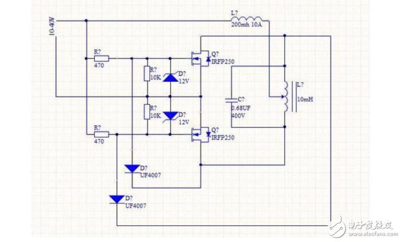


What is zero voltage switching
var videoObject = {container:'.video', variable:'player', autoplay: true, html5m3u8: true, video: "https://vdse.bdstatic.com//c6b74ee93be1c423f5465f75171da9c7?authorization=bce-aufath-v1%2Ffbe297a5cc0fb434c971b8103b %2F2017-05-11T09%3A02%3A31Z%2F-1%2F%2F54772a42ce2b3482dcac66e2c07716f94bf10fc9d9201ef594f3111a0b6a1229" }; if (!! window.ActiveXObject) {ck videoObject.html5m3u8 = new player ck what is zero voltage switch = false} player