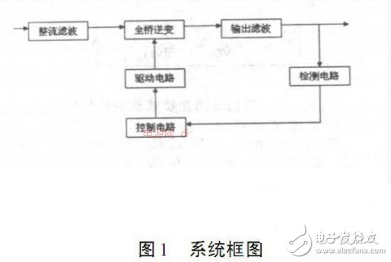
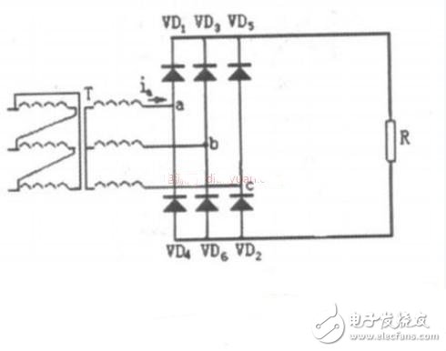
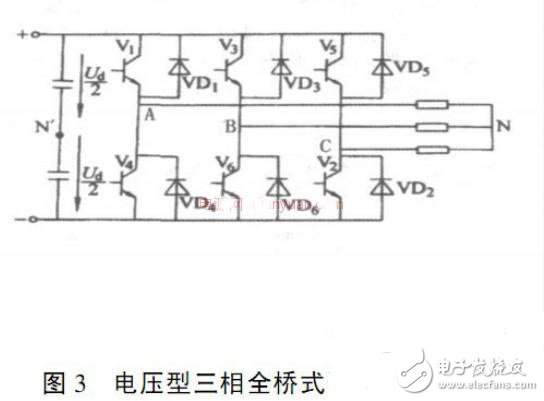
With the development of power electronics technology, the application of inverters has penetrated into various fields, and generally requires inverters to have high-quality output waveforms. Inverter output waveform quality mainly includes two aspects, namely steady state accuracy and dynamic performance. Therefore, research on inverter control schemes with simple structure and control, and excellent dynamic and static performance has always been a hot issue in the field of power electronics. With the rapid development of the national economy and the tight supply of energy at home and abroad, the development and utilization of electric energy is even more important. At present, domestic and foreign companies are vigorously developing new energy sources, such as solar power, wind power, and tidal power. Under normal circumstances, these new power generation units output unstable DC power and cannot be directly supplied to users who need AC power. To this end, it is necessary to convert the direct current into alternating current, which can be incorporated into the mains grid when needed. This DC-AC conversion requires inverter technology to complete. Therefore, inverter technology plays an important role in the development and utilization of new energy. Pulse width modulation inverter technology 1. 1 The basic principle of PWM 1. 1. 1 PWM (Pulse Width Modulation) Definition of pulse width modulation type inverter circuit: It is a circuit that controls the output voltage by changing the pulse width and controlling the output frequency by changing the modulation period. 1. 1. 2 Classification of pulse width modulation: 1. According to the polarity of the modulation pulse, it can be divided into unipolar modulation and bipolar modulation; 2. The relationship between the carrier frequency signal and the reference signal frequency The points can be divided into synchronous modulation and asynchronous modulation. 1. 1. 3 (PWM) Characteristics of the inverter circuit: The output voltage and current which are quite close to the sine wave can be obtained, so it is also called sinusoidal pulse width modulation SPWM (Sinuso idal PWM). 1. 1. 4 SPWM control mode: It is to control the on/off of the switching device of the inverter circuit, so that the output end obtains a series of pulses of equal amplitude and different width, and these pulses are used to replace the waveform required by the sine wave. Modulating the width of each pulse according to a certain rule can change the output voltage of the inverter circuit or change the output frequency. 1. 2 PWM circuit modulation control method 1. 2. 1 Definition of carrier ratio: In PWM inverter circuit, the ratio of carrier frequency fc to modulation signal frequency fr is called carrier ratio, ie N= fc/ ff . 1. 2. 2 PWM inverter circuit control mode: According to the carrier and modulation signal wave synchronization, there are two control modes: asynchronous modulation and synchronous modulation: 1. Asynchronous modulation control mode. When the carrier ratio is not an integer multiple of 3, there is an unsynchronized modulation between the carrier and the modulated signal wave. Second, synchronous modulation control mode. In the three-phase inverter circuit, when the carrier ratio is an integral multiple of 3, the carrier and the modulated signal wave can be synchronously modulated. Main circuit design This design uses the AC – DC – AC solution. Adopt SPWM modulation method. Figure 1 is a block diagram of the system main circuit and control circuit. The AC input voltage is uncontrolled and rectified to obtain a DC voltage, and then the AC output voltage is obtained through the full bridge inverter circuit. In order to ensure the reliable operation of the system and prevent the main circuit from interfering with the control circuit, the main and control circuits are completely isolated, that is, the drive signals are isolated by optocouplers, the feedback signals are isolated by transformers, and the auxiliary power supplies are isolated by transformers. 2. 1 design of rectifier circuit This design uses a three-phase bridge type uncontrolled rectifier circuit. In applications such as AC-DC-AC, uninterruptible power supply, and switching power supply, most of them use a non-controllable rectification circuit to provide direct power after capacitive filtering, which is used for inverters and inverters in the latter stage. Since the power electronic devices in the circuit use rectifier diodes, they are also called diode rectifier circuits. Its circuit diagram is as follows: The calculated diode should be HFA70NH60 rated voltage 600V, rated current 70A (fast recovery type). 2. 2 Design of the inverter circuit The inverter corresponds to the rectification, which converts the direct current into alternating current. The AC side is connected to the grid and is an active inverter. The AC side is connected to the load and is a passive inverter. The inverter circuit of this design adopts voltage type three-phase bridge inverter circuit, and its schematic diagram is shown in Figure 3. Sdec 21-75Kw Diesel Generator,Sdec Portable Power Generator,Sdec Open Type Power Generator,Sdec Container Power Generator Shanghai Kosta Electric Co., Ltd. , https://www.generatorksd.com

