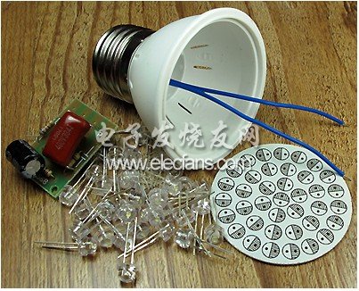
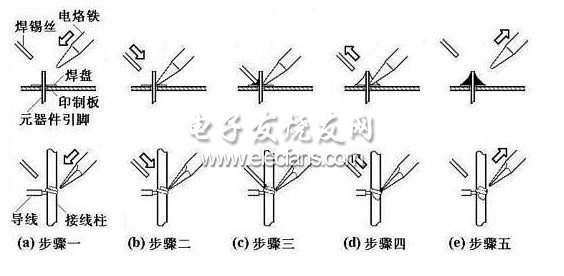
material: This article refers to the address: http:// 1, 40 astigmatic white high-brightness straw hat LED (LED specification: 3.2 ~ 3.4V current less than 20 mA brightness 1400MCD) 2, assembled plastic casing and E27 Luokou lamp holder and lead out the wire 3, 38 LED light board PCB 4, a good welding power board     First, you can solder the LED panel. Before printing, carefully polish all the pads of the LED with a drawing eraser. This will remove the oxide layer on the PCB and ensure reliable soldering! Insert the white LED carefully according to the polarity marked on the PCB. PCB, note: the pin with the short pin is inserted into the hole marked with shadow on the PCB. When soldering LEDs, please use 30W pointed soldering iron soldering without leakage. You can solder one LED of the LED and then observe the position of the LED. If it is not right, you can melt the solder in time to confirm the position and then solder another lead. foot. The welding should be carried out simply and decisively. The welding time should not be too long. It should be controlled within 2 seconds, otherwise the LED may be soldered! We specially provide 2 LEDs, which can be replaced when it is accidentally damaged by beginners. After soldering, please check the lamp board for solder joints. Is there a bridge short circuit? Are the LEDs all on the same plane? Are there any extra solder balls scattered on the PCB? Basic steps for manual soldering operations: Master the soldering iron temperature and soldering time, and choose the proper soldering iron tip and solder joint contact position to get a good solder joint. The correct manual soldering process can be divided into five steps:     (1) Step 1: Prepare the welding diagram (a) Hold the welding wire in the left hand and hold the soldering iron in the right hand to enter the welding state. The tip is required to be clean, free of oxides such as slag, and coated with a layer of solder on the surface. (2) Step 2: Heating the weldment (b) The iron head is placed at the joint of the two weldments to heat the entire weldment for about 1 to 2 seconds. For soldering components on a printed board, care should be taken to allow the soldering iron tip to simultaneously touch two soldered objects. For example, the wires in Figure (b) and the terminals, component leads and pads should be uniformly heated at the same time. (3) Step 3: Feeding the wire diagram (c) When the welding surface of the weldment is heated to a certain temperature, the solder wire contacts the weldment from the opposite side of the soldering iron. Note: Do not send the solder wire to the soldering iron! (4) Step 4: Remove the welding wire (d) After the welding wire has melted a certain amount, immediately remove the welding wire to the upper left 45° direction. (5) Step 5: Remove the soldering iron (e) After soldering the soldering pad and the soldering part of the soldering piece, remove the soldering iron to the upper right 45° direction to end the soldering. From the third step to the end of the fifth step, the time is also about 1-2 seconds.     Solder the two blue flexible wires from the lamp cap to the two pads labeled “R†on the power supply board. The M end of the power supply board is connected to the center pad of the LED board, and the B end is connected to the outer ring pad of the LED board. . Finally, the hole reserved on the power board is placed on the fixed plastic column in the lamp housing, and the power board can be fixed by ironing the plastic column with a soldering iron. The LED light board can be stuck in the lamp housing. Generally, the power board and the LED light board can be separately fixed by the hot sol to prevent sloshing and accidental short circuit. The LED light is not only very light and not easy to break, and the energy-saving lamp with brightness equivalent to 5W is still very beautiful! Note on production: Please carefully test the power after many times, pay attention to personal safety, beware of electric shock! Common malfunctions: Because this lamp has a large number of LEDs, it is easy to cause all of the LEDs to be damaged or the LED pins and PCBs to be soldered poorly, so the key to the success of the production is to be careful when soldering the LEDs. The method of troubleshooting is as follows: Using a multimeter DC 250V voltage measurement, the black bar is fixed at M point, and the red bar measures the voltage of each LED terminal from point B. (When measuring, pay attention to safety. At this time, the whole circuit board and AC mains are not isolated, touch plate There is danger of electric shock on the upper part!) If the voltage disappears, this LED is damaged (such as reverse mounting, LED die opening, LED pad root short circuit, LED blank soldering, etc.), you can also use DC voltage detection LED, first thoroughly Disconnect the AC power! Then, if you use a DC voltage of about 10V, the four LEDs are connected in series and then powered on, which can quickly determine the fault. Perkins ≥1000KW Diesel Generator Perkins ≥1000KW Diesel Generator,Perkins Power Generator,Perkins Genset,Perkins Open Diesel Generator Shanghai Kosta Electric Co., Ltd. , https://www.shkostagenerator.com


