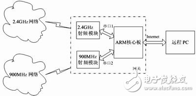
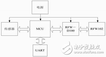
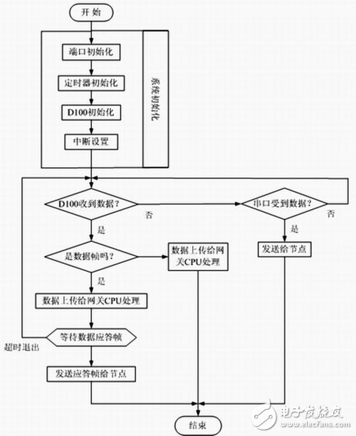
Wireless sensor networks can monitor, perceive, and collect information about various environments or monitored objects in the network distribution area in real time, and process this information to obtain detailed and accurate data and transmit it to users who need this information. At present, the main research areas in this field are MAC layer protocols and network layer routing protocols. To carry out these two aspects of research, a physical experiment platform is necessary. Overall design This paper designs and implements a relatively complete wireless sensor network demonstration system, which mainly includes node machines, gateway machines and database systems. This system realizes the collection, transmission, processing and database management of remote environmental data. And after a large increase in the number of nodes, it can also be used as a development platform for the sensor MAC layer and network layer protocol. The system composition block diagram is shown in Figure 1. In the sensor node network part, there are two subnets, each of which works independently and runs in different frequency bands, one is 2.4GHz and the other is 900MHz, both of which are frequency bands specified by the ZigBee standard. 2.4GHz hardware mainly adopts 89lV52 single-chip microcomputer and RFW102 radio frequency module of RFwave company. What 900MHz uses is 89lV51 one-chip computer plus NRF905 radio frequency module. In the sensor part, both nodes are designed as pluggable universal interfaces. Currently, they support temperature and humidity sensors, electromagnetic intensity sensors, and air quality sensors. Both subnets are connected to an ARM gateway, which is coordinated and processed by the gateway. The ARM gateway uses the S3C44B0X development board plus 2.4GHz and 900MHz radio frequency modules. The radio frequency module and the ARM board use serial ports for connection and communication. The other end of the ARM gateway is connected to a remote PC through a network port. Data is transmitted in the network via UDP. The database system is established on a remote PC, and users can perform inquiries and related operations. The database is established by Microsoft ACCESS, and the interface is written by delphi. Figure 1 System composition block diagram This text designs two kinds of nodal machines, one kind works in 2.4GHz frequency band, the other kind can work in two frequency bands of 868MHz and 915MHz. 2.4GHz band node machine design The hardware part is shown in Figure 2, including power supply, MCU, sensor, RFW-D100 and 102. Among them, MCU is the main control device, and the sensor is designed to be separable, which can insert a variety of sensors. RFW-D100 and 102 jointly form the radio frequency part to complete wireless data transmission and reception. UART can be used when debugging hardware. When the board is used as the radio frequency module of the gateway machine, the UART completes the communication with the ARM board. The power supply is designed into two power supply modes: battery and external power supply. Figure 2 Hardware block diagram of 2.4GHz node machine 1. Power supply section In order to facilitate debugging, the power supply is designed as a dual power supply mode, that is, an external stabilized power supply and battery power supply. The advantage of this design is that it can be powered by an external regulated power supply when the board is debugged, without a battery, which reduces development costs and is more stable. After the board is successfully debugged, battery power can be used in actual operation. Of course, this design will also increase the board area and increase the number of components. When the actual product is made, the power supply circuit of the regulated power supply can be removed to reduce the volume and cost. The regulated power supply circuit adopts 9V DC input, which is converted into 5V by 7805, and then converted into 3.3V by AAT3221 power conversion chip. Select TPS60101 in the battery voltage regulator part. This is a chip especially suitable for regulating battery-powered systems. As for which way to supply power is determined by the jumper. 2. MCU MCU chooses 52 one-chip computers, the model is 89lV52. It has 256Byte RAM and 8kB flash, 3 16-bit timers, which is more suitable for this application. 3. RF part The radio frequency part uses RFW102 of RFwave Company, this is a radio frequency module that works in 2.4GHz frequency band, power consumption is low, and the highest speed can reach 1Mbps. It is simple and convenient to use with RFW-D100. 4. Sensor The interface of the sensor part is designed as a pluggable universal interface, which is convenient to expand other sensors. Take the temperature/humidity sensor as an example. This article uses Sensirion's SHT71, which is a digital sensor with low power consumption and integrated temperature/humidity. Easy to use. Design of Node Machine in 868MHz and 915MHz Frequency Band nRF905 1.0 is powered by 9V DC power supply and battery. A single-chip microcomputer is used as the central control unit to control sensors and wireless transceiver modules. And with additional memory, it can realize the store and forward function. nRF905 1.0 can be divided into 5 major parts: 1. Central control unit: Use a piece of AT89LV52 as the central control unit. Among them, R1OUT, T1IN pins are used for serial communication. 2. Power supply: DC 9V power supply and battery power supply can be selected, and the power supply mode can be switched by jumper. 3. Memory: Use a piece of AT24C21 as the memory. When the amount of data exceeds the capacity of the single-chip microcomputer or the wireless channel is abnormal, the data can be temporarily stored in the memory for later forwarding. 4. Sensor: Use Sensirion's SCH7x temperature/humidity sensor. 5. Wireless transceiver module: use Nordic's nRF905 wireless transceiver chip, which can work in three frequency bands of 433MHz, 868MHz and 915MHz. Figure 3 Software flow chart of the radio frequency module hardware design The hardware of the gateway machine adopts the embedded system development board based on ARM7TDMI, plus two wireless radio frequency modules based on RFW-D100 and 102 and nRF905. The schematic diagram of the structure is shown in the middle part of Figure 1. The main consideration of this design is to save development time. The two radio frequency module daughter boards and the ARM board communicate through serial ports. 1. Microprocessor S3C44B0X S3C44B0X is a 16/32-bit RISC processor launched by Samsung. It uses an ARM7TDMI core, a 0.25mm process CMOS standard macrocell and a memory compiler. Its low power consumption and fully static design are particularly suitable for cost- and power-sensitive applications. S3C44B0X also adopted a new bus structure, namely SAMBAâ…¡. 2. UART asynchronous serial interface S3C44B0X's UART (Universal Asynchronous Receiver Transmitter) unit provides two independent asynchronous serial I/O ports, each of which can work in interrupt and DMA modes. The highest rate they support is 115.2kbps. Each UART contains a baud rate generator, transmitter, receiver and control unit. In the design of this system, the two serial ports are connected to two radio frequency modules, respectively, and work in the 2.4GHz, 868MHz, and 900MHz frequency bands. In this way, the processor can communicate with the two subnets through these two channels. 3. Ethernet controller RTL8019AS The RTL8019AS highly integrated Ethernet controller chip produced by Realtek integrates the performance of the media access control sublayer (MAC) and the physical layer. It can easily design a system based on the ISA bus and simply interface with the general-purpose single-chip microcomputer. In addition, it also has the advantages of compatibility with NE2000, good software portability, and low price. It occupies a considerable proportion of the 10Mbps network cards on the market. In this system, the network port is connected to the Ethernet, and the data collected by the gateway is uploaded to the database of the PC. 4. Flash memory The Flash used in this system is a memory with 16Mb (2MB) and a single 5V power supply. The 2MB data area is divided into 32 64kB sections, so it has a flexible erasing function. Flash is used to store program code in this system. After the system is powered on or reset, the instructions are fetched from here and executed. As can be seen from Figure 1, the gateway machine part is composed of an ARM development board and two radio frequency modules to complete the data acquisition, processing and uploading tasks of the two subnets. The radio frequency module is not designed separately, but a simplified version of the node machine of the two frequency bands. The data collection part is removed to shorten the development cycle and provide versatility. In the case of the same hardware, as long as the software of the two modules is modified, the function of wireless data transmission and reception can be completed. The specific hardware design can refer to the hardware design of the previous node machine. The wireless sensor network gateway machine is divided into three relatively independent units in hardware as described above, so the software is also divided into three relatively independent parts. 1. ARM board software The software of the ARM core board includes initialization, processing sampling commands from the upper PC, and sending sampling commands to two subnets through two serial ports. Then wait for the data information uploaded by the node. The key is how to handle the data information uploaded by the two subnets through the two serial ports. Not leaking, not heavy. Due to space limitations, the specific process will not be detailed here. 2. RF module software The software flow of the radio frequency module is shown as in Fig. 3. The ARM board is connected to two radio frequency modules with different subnets through two serial ports, so as to have the ability to communicate with the two subnets. Choose Access database platform and ADO database connection technology, and use Delphi programming language to realize interface, management, query operation and data transmission and reception on the internet. Delphi is a powerful rapid application software development program, which integrates ADO database connection controls and network processing controls, which can quickly and easily develop software. After about half a year of hard work, with the joint efforts of the team members, we completed the design and implementation of the first version of the wireless sensor network experimental demonstration system, and successfully passed the temperature/humidity information of the four remote nodes through the two frequency bands. The channel is transmitted to the database, and can be inquired and managed. Of course, the first version still has many areas that need to be improved and improved, such as the modularization of the underlying hardware operation functions, the selection of a more powerful MCU for the node machine, the improvement of the database, and so on. Insulated Terminals,Terminals,High-quality insulated terminals Taixing Longyi Terminals Co.,Ltd. , https://www.longyicopperlugs.com introduction

