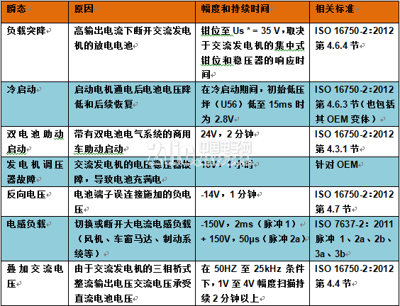
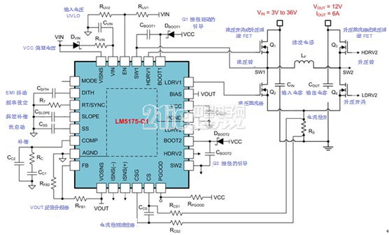
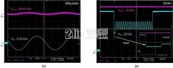
Automotive batteries have a steady-state voltage range of 9V to 16V, depending on their state of charge, ambient temperature, and alternator operating conditions. However, battery power buses are also subject to a wide range of dynamic disturbances, including start-stop, cold-start, and load dump transients. This article refers to the address: http:// In addition to the standard pulse waveforms given by industry standards such as the International Organization for Standardization (ISO) 7637 and ISO 16750, each car manufacturer has a unique and extensive test suite for conducted immunity. Table 1 lists several transient characteristics of undervoltage and overvoltage vehicles. Table 1: Continuous and transient conducted interference of automotive batteries and related test levels Generator induced noise In the audio range, a particularly annoying source of noise is the automotive alternator, where the residual AC generated at the output causes the alternator to emit "beep" and power modulation problems. Section 4.4 of ISO 16750-2 mentioned in Table 1 describes the ripple voltage of the alternator output over a frequency range of 50 Hz to 25 kHz with peak amplitudes (VPP) of 1 V, 2 V and 4 V, depending on the test pulse severity. See Figure 1. Figure 1: ISO 16750-2 superimposed AC voltage test (a); log frequency sweep curve from 50 Hz to 25 kHz over a two minute scan duration (b) In many vehicles, a centralized passive circuit protection network consisting of low-pass inductor-capacitor (LC) filters and transient voltage suppressor (TVS) diodes is used as the first line of defense against transient disturbances. Automotive electronics located downstream of the protection network are rated to withstand transients of up to 40V without damage. However, the cutoff frequency required by the LC filter attenuates low frequency interference, resulting in considerable filter inductance and electrolytic capacitance. At this point, the presence of an active power stage is necessary to eliminate bulky passive filter components and provide a compact and cost-effective solution for compact voltage regulation and transient suppression. Four-Switch Synchronous Buck-Boost Regulator The advantage of the wide VIN buck-boost regulator solution is its high power supply rejection ratio (PSRR), which provides excellent transient mechanics to attenuate input voltage transients. With this in mind, I recently wrote an article: "Automotive Front-End Buck-Boost Regulator Active Filtering Voltage Interference", which describes a high-density solution for automotive applications. Figure 2 shows the schematic of a four-switch buck-boost regulator for a tightly regulated 12V rail. The solution is ideal for critical automotive functions, including drive trains, fuel systems, and body and safety subsystems, even during the most severe battery voltage transients, the load must remain powered without failure. This easy-to-use design tool simplifies the design of the regulator, resulting in faster design and time-to-market. Figure 2: Four-Switch Synchronous Buck-Boost Solution with 3V to 36V Wide VIN Range Figure 3a shows the output voltage waveform of a buck-boost regulator when the 9V DC input has a superimposed sinusoidal ripple with a 1V peak amplitude and a 1kHz frequency. The input ripple is attenuated by approximately 40 dB. Figure 3b shows the output voltage dropped to 3V during the cold start transient using the automotive cold start simulator for 20ms. The four-switch buck-boost converter seamlessly regulates the cold start curve. Figure 3: Measured four-switch buck-boost converter: 9V DC input (a) ripple rejection; cold start performance (b) to sum up With its high supply voltage rejection ratio (PSRR), high efficiency, and low overall bill of materials cost, quad-switched synchronous buck-boost, like TI's LM5175-Q1 current mode controller, provides a way to mitigate transient interference in automotive applications. A useful solution. The buck-boost controller is certified in the automotive industry for easy integration into automotive 12V single cells and 24V dual battery systems. REMOTE CONTROL SOCKET
Programming Instructions
•Press any ON switch on the Remote Control for approximately 2 seconds and the Remote Socket(s) learn the code. The LED will stop flashing top confirm the codehas been accepted. Remote Control Plug Socket,Remote Controlled Mains Outlet,Remote Control Plug Adapters,Remote Control Sockets,Remote & Smart Controlled Sockets,Electric Sockets Plus Remote Control NINGBO COWELL ELECTRONICS & TECHNOLOGY CO., LTD , https://www.cowellsockets.com


Important Safeguards
When using any electrical appliance, in order to reduce the risk of fire, electric shock and/or injury to persons, basic safety precautions should always be follow8d. including:
• The appliance is for household and indoor use only.
• Before plugging in. check that the voitage on the rating label is the same as the mains supply.
• To protect against electric shock, do not immerse any part of the product in water or other liquid.
• This socket is intended for use by competent adults only and children should be supervised at all times.
• Do not use the socket for other than its intended use.
• This socket can be used by children aged from 8 years arxl above and persons with reduced physical, sensory or mental capabilities or lack of experience and knowledge if they have been given supervision or instruction concerning use of the appliance in a safe way and understand the hazards involved. Children shall not p<ay with the appliance Cleaning and user maintenance shall M be made by children without supervision.
• Children of less than 3 years should be kept away unless continuously supervised.
Children from 3 years and less than 8 years shall only switch on/off the appliance provided that it has been placed or installed in its intended normal operating position and they have been supervision or instruction concerning use of the appliance in a safe way and understand the hazards involved. Children aged from 3 years and less than 8 years shall not plug in. regulate and clean the appliance or perform user maintenance.
• Don't use this socket in the immediate surroundings of a bath, a shower or a swimming pool.
• In case of malfunction, do not try to repair the socket yourself, it may result in a fire hazard or electric shock
Do Not Exceed Maximum a680W
Place the LR44 batteries provided into the compartment in the back of the Remote Control, please insert as sho*/m in the back of the compartment to ensure the polarity is correct.
• Plug the Remoce Socket$($)lnto the wall socket(s) and switch on the mams supply, the red LED will flash every second.
• If the LED is not flashing press & hold the manual ON/OFF button for 5 seconds until it Hashes
• Any number of Remote Sockets can be programmed to one Remote Control ON button to create multiple switching.
• To programme o<her Remote Sockets on different Remote Control ON buttons repeat the prevous steps
• If the mains supply is turned off the Remote Sockets v/ill lose their code and it wil be necessary to re-pcogramme.
Operation:
• Plug your appliance(s) into the Remote Socket(s)
• Press the programmed ON or OFF button on the Remote Control to control the Remote Socket.
♦ The Remote Sockets can also be operated manually using its ON/OFF Button Trouble shooting
If a Remote Socket does not react to the Remote Control please check the followng:
♦ Low battery in tbo Remote Control
• Distance too large between the remote control and the recerver (ensure the range distance is no more than 20 clear Metres) and free from obstacle that may reduce the distance.
• If programming has not been successful, tum the power off and back on then follow the programming steps above.
How to decode
• Press the manual ONX)FF button for 5 seconds until the red LED flashes once per
second to confirm de-coding is successful
♦ Press the ALL OFF switch on the Remote Control for more than 3 seconds, the LED
flashes once per second to confirm (decoding successful.
Voltage: 240V-/50HZ
Max power rating: 3680W max.
Remote frequency:
Remote range:
Battery Type:
433.92MHz
230 Metres
Button Cell 2x1.5V LR44 =
Please check with your local waste management service authority regarding regulations for the safe disposal of the batteries. The batteries should never be placed G municipal waste.
Use a battery d^posal facility if available
M
For eioctncal products sold within the European Community. At the end of the electrical products useful life, it should not be disposed of wth household waste. Please recycle faaMies exist. Check with your Local Authonty or retailer for recycling advice.
C€