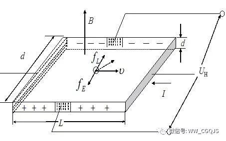
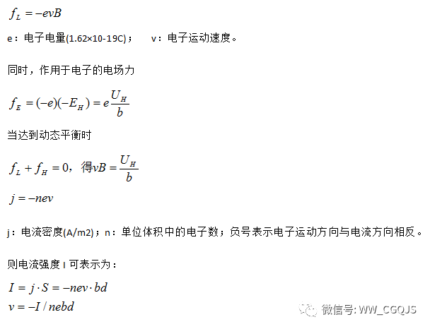
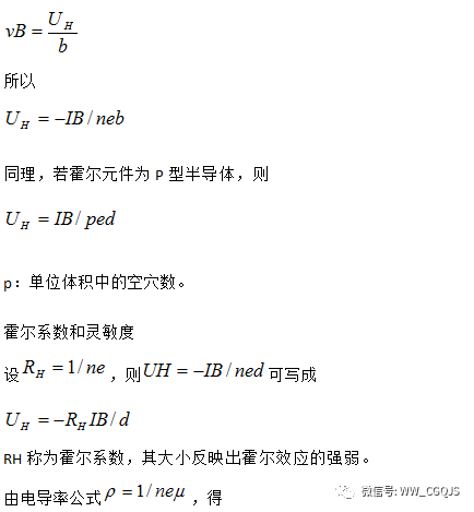
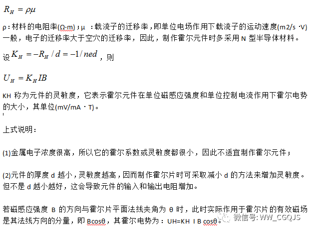
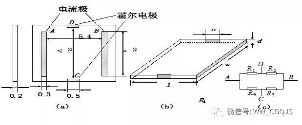
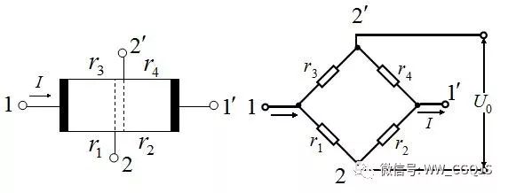
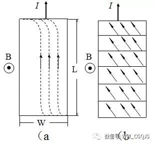
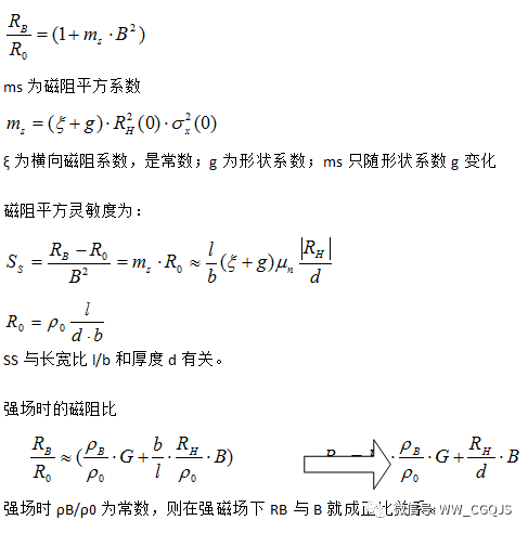
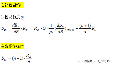
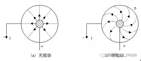
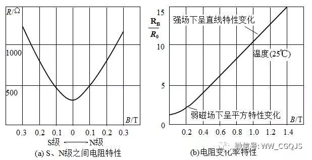
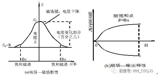
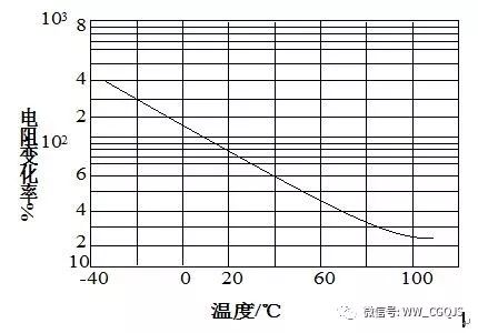
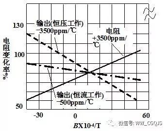
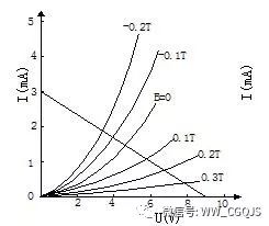
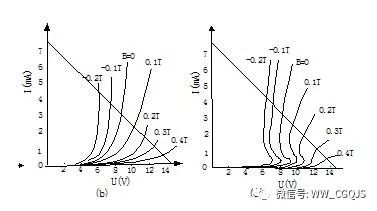
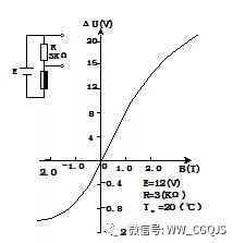
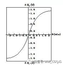
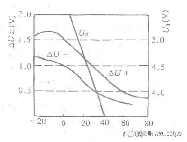
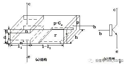
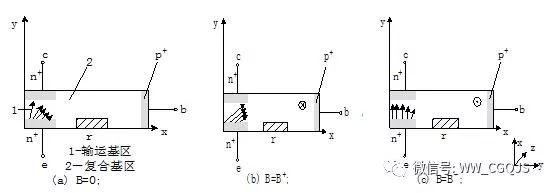
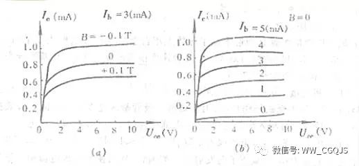
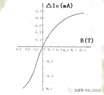
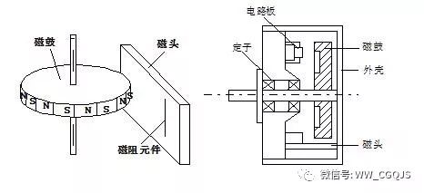
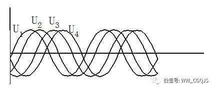
A magnetic sensor is a device that converts magnetic field information into various useful signals. It is the core of various magnetic measuring instruments. In order to detect and utilize magnetic enthalpy, various magnetic measuring instruments have been developed. So far, more than ten commonly used magnetic measuring methods have been formed, and dozens of large-scale magnetic measuring instruments have been developed and produced. The general magnetic measuring instruments are composed of a magnetic sensing element, a converter, a signal processing circuit and a readout circuit. The basic performance of the instrument (eg sensitivity, dynamic range, accuracy) is primarily determined by its sensors. The signal processing circuit can provide functions such as amplification, conversion (such as F/V, A/D conversion, etc.), compensation, and correction. With the development of magnetic materials, people use various magnetic materials as information carriers, such as computer information storage, audio and video information to record various object motion information, including position, displacement, speed, speed, etc., can be based on magnetic bodies As a carrier. A large variety of magnetic read, write and sense devices are therefore required. Thereby, the magnetic sensor is gradually separated from the magnetic measuring instrument to form an independent magnetic sensor product. The magnetic sensor industry is developing rapidly. It can be said that "any computer, a car, or a factory that leaves the magnetic sensor will not work properly." At the same time, magnetic sensors have penetrated into people's daily lives, and many household appliances use magnetic sensors in large quantities. The application of magnetic sensor is expanding and its status is becoming more and more important. According to its structure, it is mainly divided into two types: body type and knot type. The former represents a Hall sensor, and the latter represents a magnetic sensitive diode, a magnetosensitive transistor, and the like. They are all magnetic sensors made by the use of carriers inside the semiconductor material to change the direction of motion with the magnetic field. There is also a magnetoelectric sensor made using the principle of electromagnetic induction. Hall sensor Hall Effect A static current-carrying conductor or semiconductor placed in a magnetic field, when its current direction and magnetic field direction are inconsistent, an electromotive force is generated between the two faces of the current-carrying conductor perpendicular to the direction of the current and the magnetic field. This phenomenon is called the Hall effect. . This electromotive force is called the Hall potential, and the current-carrying conductor (mostly a semiconductor) is called a Hall element. The Hall effect is the result of lateral drift of carriers in a conductor in the magnetic field by Lorentian forces. As shown in the figure, a current I is passed through a semiconductor wafer perpendicular to the magnetic field, and it is assumed that the carrier is an electron (N-type semiconductor material) which moves in a direction opposite to the current I. Due to the Lorentz force fL, the electrons will deflect toward one side (as in the direction of the dashed arrow) and cause the electrons to accumulate on the modified side. On the other side, positive charge buildup is formed, and the lateral direction of the element forms an electric field. The electric field prevents the electrons from continuing to shift to the side, and when the electric field force fE received by the electrons is equal to the Lorentz force fL, the electron accumulation reaches a dynamic balance. At this time, the electric field established between the lateral faces of both ends is called the Hall electric field EH, and the corresponding potential is called the Hall potential UH. Let the Hall piece have a length L, a width b, and a thickness d. It is also assumed that the electron moves at a uniform velocity v, and it is subjected to Lorentz force under the action of the magnetic induction B applied in the vertical direction. also because When the direction of the control current or the direction of the magnetic field changes, the direction of the output Hall potential also changes. But when the magnetic field changes direction with the current, the Hall potential does not change direction. Generally, when applied, the voltage applied across the Hall plate is E. If the current I in the Hall potential is rewritten to E, the calculation is convenient. It can be seen from the above formula that the Hall potential UH value can be changed by appropriately selecting the material mobility (μ) and the aspect ratio (b/L) of the Hall sheet. Hall element structure Device Current (Control Current or Input Current): Current flowing into the device. The current terminals A, B are correspondingly referred to as device current terminals, control current terminals or input current terminals. The terminals C and D at the Hall output are correspondingly referred to as Hall terminals or Hall electrodes and output terminals. If the load is connected between the Hall terminals, it is called Hall load resistance or Hall load. The resistance between the current electrodes is called the input resistance or the internal resistance is controlled. The resistance between the Hall terminals is called the output resistance or the Hall side internal resistance. Hall element characteristics UH-I characteristics When the magnetic field (B) is constant, the control current I and the Hall potential UH are measured at a certain temperature, and a good linear relationship can be obtained. The slope of the line is called the control current sensitivity, expressed as KI. As a result, the element having a large sensitivity KH has a control current sensitivity KI which is generally large. However, UH, which is a sensitive component, is not necessarily large, because UH is also related to I. UH-B characteristics When the control current I remains unchanged, the open Hall output of the component does not fully exhibit a linear relationship with the increase of the magnetic field, but has a nonlinear deviation. Error analysis and compensation method 1. Influence of component geometry and electrode solder joint size on performance 1 geometric size impact on performance In the analysis of the Hall effect principle, we consider the length L of the Hall piece as infinity. In fact, the length of the Hall plate is limited. If L is too small, when it is small to a certain limit, the Hall electric field will be short-circuited by the control current, so adding an item and geometry to the expression of the Hall potential Size dependent factor, Experiments show that when L/b>2, the shape factor fH(L/b) is close to 1. In order to improve the sensitivity of the component, the L/b value can be appropriately increased, and it is sufficient to take L/b=2 in actual design. 2 electrode solder joint size impact on performance The size of the Hall electrode also has a certain influence on the output of the Hall potential. According to the requirements of the ideal component, the electrode that controls the current should be in good surface contact with the Hall element, while the Hall electrode is in point contact with the Hall element. In fact, the Hall electrode has a certain width l, which has a large influence on the sensitivity and linearity of the element. Studies have shown that when l / L < 0.1, the effect of electrode width is negligible. 2. Unequal potential U0 and its compensation When making a Hall element, it is impossible to ensure that the Hall electrode is soldered on the same equipotential surface. As shown in the figure, when the control current I flows through the component, even if the magnetic induction is equal to zero, there is still a potential at the Hall potential. The potential is called the unequal potential U0. The unequal potential is the main cause of the zero error. The equivalent circuit is shown in the figure. If the two Hall electrodes are on the same equipotential surface, r1=r2=r3=r4, the bridge is balanced, U0=0. When the Hall electrodes are not on the same equipotential surface (Fig. 2.1.3), the bridge balance is destroyed due to the increase of r3 and the decrease of r4, so that U0≠0. There are various ways to reduce the unequal potential to achieve compensation. Semiconductor magnetoresistive sensor A magnetoresistance is a magnetosensitive element whose resistance changes with the change of the magnetic field, also called an MR element. Its theoretical basis is the magnetoresistance effect. Magnetoresistance effect A magnetoresistance is a magnetosensitive element whose resistance changes with the change of the magnetic field, also called an MR element. Its theoretical basis is the magnetoresistance effect. If a sheet of metal or semiconductor material with current is applied to an external magnetic field perpendicular or parallel to the current, the resistance value increases. This phenomenon is called the magnetoresistance change effect, which is referred to as the magnetoresistance effect. In a magnetic field, the flow path of the current is lengthened by the action of the magnetic field, causing the resistivity of the material to increase. If the mobility of two kinds of carriers (electrons and holes) of a certain metal or semiconductor material is very different, the resistivity changes mainly caused by a carrier having a large mobility, which can be expressed as: B—— is the magnetic induction strength; Ρ——the resistivity of the material when the magnetic induction is B; Ρ0——the resistivity of the material when the magnetic induction is 0; μ - the mobility of the carriers. When there is only one type of carrier in the material, the magnetoresistance effect is almost negligible, and the Hall effect is more intense. If the material exists in both electrons and holes (such as InSb), the magnetoresistance effect is strong. The magnetoresistance effect is also closely related to the shape and size of the sample. This magnetoresistance effect related to the shape and size of the sample is called the geometric magnetoresistance effect of the magnetoresistance effect. Rectangular magnetoresistive devices only in L (length) Figure (a) shows the case where there is no grid, the current is deflected only near the electrode, and the resistance increase is small. A plurality of parallel equidistant metal strips (ie, short-circuit grids) are formed on the L>W rectangular magnetoresistive material to short-circuit the Hall potential. The grid magnetoresistive device is equivalent to that shown in Figure 2.2.1(b). In many flat strips of magnetoresistance in series. Therefore, the grid magnetoresistive device increases the value of the zero field resistance and increases the sensitivity of the magnetoresistive device. Commonly used magnetoresistive elements are semiconductor magnetoresistive elements and strong magneto-resistive elements. The interior has various forms such as a half bridge or a full bridge. Magnetoresistive element Rectangular magnetoresistive element; The physical magnetoresistance effect and the geometric magnetoresistance effect exist simultaneously. Magnetoresistance ratio in weak field Grid type varistor → high sensitive resistance g' is the shape factor of the sub-element, and g' is much enhanced, then msn increases and RBn increases. Cobino component structure type Disc member A current electrode is arranged around the center and the outer circumference. principle: Current flows between the two electrodes; The motion path of the carrier is bent by the magnetic field; Increased resistance Characteristics of magnetoresistors Sensitivity characteristics The sensitivity characteristic of the magnetoresistive element is expressed by the rate of change of resistance at a certain magnetic field strength, that is, the slope of the magnetic field-resistance characteristic. Commonly used K means that the unit is mV/mA.kG or Ω.Kg. In the calculation, RB/R0 is commonly used. R0 represents the resistance value of the magnetoresistive element in the absence of a magnetic field, and RB is the resistance value exhibited by the magnetoresistive element when 0.3T magnetic induction is applied. In this case, the general reluctance The sensitivity of the component is greater than 2.7. Magnetic field - resistance characteristics The resistance value of the magnetoresistive element is independent of the polarity of the magnetic field, and it increases only as the strength of the magnetic field increases as shown in (a). In the weak magnetic field below 0.1T, the curve exhibits a square characteristic, and after a value of more than 0.1T, it exhibits a linear change as shown in (b). Strong magnetic reluctance element resistance - magnetic field characteristic curve It can be seen from the figure that it is opposite to the curve of the magnetoresistive element, that is, as the magnetic field increases, the resistance value decreases. And it is saturated at a magnetic flux density of several tens to several hundreds of Gauss. Generally, the resistance changes by a few percent. Resistance - temperature characteristics As can be seen from the figure, the temperature characteristics of the semiconductor magnetoresistive element are not good. The resistance value in the figure is reduced by 1/2 in the range of variation of 35 °C. Therefore, in application, it is generally necessary to design a temperature compensation circuit. Resistance of the ferromagnetic resistance element - temperature characteristic curve: The temperature characteristics of the constant current and constant voltage power supply modes are shown in the figure. Good current characteristics of –500ppm/°C are achieved with constant current supply and up to 3500ppm/°C with constant voltage supply. However, since the ferromagnetic reluctance element operates in a switching mode, a constant voltage method is commonly used. Junction magnetic sensor Magnetic sensitive diode structure The junction type magnetic sensor is a PIN type diode, which can be called a junction type two-terminal device (also called a Sony diode SMD) with highly doped P+ and n+ regions at both ends; a longer intrinsic region I is called a long base. The region diode, one side of the I is ground smooth; the other side is made of a diffusion region or a sandblasting method to form a high recombination region (referred to as an r region), so that the electron-hole pairs are easily recombined on the rough surface and disappear. When a positive bias is applied, the p+-I junction injects holes into the intrinsic region I, and the n+-I junction injects electrons into the intrinsic region I, which is also referred to as a double implanted long diode. working principle Figure (a) shows no current, a large amount of holes are applied from the p+ region through the I into the n+ region, and a large amount of electrons enter the p+ region from the n+ region through I to form a current. Only a small amount of electrons and holes in the I region are compounded. Figure (b) When the magnetic field B+ (forward) is applied, the electrons and holes are deflected by the FL to the r region, and the recombination in the r region causes the current in the I region to decrease, the resistance to increase, and the voltage drop in the I region to increase, n+-I. The voltage drop across the junction and p+-I junction is reduced, causing the injected carriers to decrease again until the forward current decreases to a certain stable value. Figure (c) When subjected to the magnetic field B-(reverse), the voltage drop across the n+-I and p+-I junctions increases, causing the injected carriers to increase and the current to increase further until the current reaches saturation. Under the forward voltage, when the forward magnetic field and the reverse magnetic field are applied, the forward current of the PIN tube changes greatly, and the magnitude of the magnetic field is different, and the current changes are also different. Main characteristics of magnetic diodes 1. Volt-ampere characteristics--the relationship between forward bias and current The volt-ampere characteristic curve of the Ge magneto-sensitive diode has a certain output voltage. When the magnetic field is positive, the current decreases with the increase of the magnetic field. When the magnetic field is negative, the current increases with the negative direction of the magnetic field. The larger the voltage is, the larger the output current changes. The bigger. Figure (b, c) shows the volt-ampere characteristics of a silicon magnetic diode. Figure (c) has a negative resistance characteristic, that is, the current increases sharply, and the bias voltage suddenly drops; because the high-resistance I region has less thermal equilibrium carriers, the carriers injected into the I region do not generate larger before filling the composite center. The current is only increased after the current is filled, and the voltage drop in the I region is reduced, showing a negative resistance characteristic. 2, magnetoelectric characteristics The relationship between the amount of change in the output voltage of the magnetosensitive diode and the applied B under given conditions. There are often two ways to use single and complementary. The forward magnetic sensitivity is greater than the reverse when used alone. When used in complementary, the positive and negative magnetic sensitivity curves are symmetrical and have good linearity under weak magnetic fields. Single use Complementary use 3, temperature characteristics The output voltage variation ΔU varies with T under standard test conditions. 4, four common compensation circuits Complementary temperature compensation circuit diagram (a); differential temperature compensation circuit diagram (b); full bridge temperature compensation circuit diagram (c); thermistor temperature compensation circuit diagram (d). Magnetic triode structure Emitter e, base b, collector c; a high recombination zone r is formed on one side of the emitter and long base sections. working principle When the magnetic field strength B changes, the changes of the base current Ib, the collector current Ic, and the current amplification factor β are analyzed. Figure (a): When B = 0, since the width of the base region is larger than the effective diffusion length of the carrier, a small number of carriers injected into the emitter region input c, most of which form Ib through epb, Ib > Ic, current amplification factor β < 1. Figure (b): When subjected to the forward magnetic field (B+), the carrier is deflected by the action of FL to the side of the emission region, causing the IC to drop significantly, while the base region is compounded, the amount of Ib is small, and the current amplification factor is β. Reduced. Figure (c): When the reverse magnetic field (B-) acts, the carrier is deflected by the action of FL to the side of the collecting area, so that the IC increases, the composite of the base region decreases, β increases, and IB hardly changes. Main characteristics of magnetic sensitive transistors 1, volt-ampere characteristics 2, magnetoelectric characteristics Ic and B are linear relationships in weaker magnetic fields 3, temperature characteristics 3ACM 3BCM magnetic sensitivity temperature coefficient is 0.8% ∕ °C The temperature coefficient of 3CCM magnetic sensitivity is -0.6% ∕ °C 4, frequency characteristics Magnetic field alternation 3BCM response t=2us cutoff frequency 500KHz 3CCM response t=4us cutoff frequency 2.5MHz New magnetic sensor High resolution magnetic rotary encoder There are two types of coding and absolute and incremental. Absolute: Converts the absolute position of the measured point directly into a binary digitally encoded output. The power is turned off in the middle, and the data of the current position can be read after re-powering. Incremental: The measured output is the difference between the current state and the previous state. It is usually output in the form of a pulse number, and then the number of pulses is counted by a counter. It is necessary to specify the pulse equivalent (the value of the measured physical quantity represented by one pulse) and the zero mark (the measured starting point mark). The absolute position of the moving parts cannot be known by power failure in the middle. The magnetoresistive magnetic encoder has the advantages of compact structure, stable operation at high speed, strong anti-pollution ability, strong anti-vibration and anti-explosion ability, and low power consumption. The magnetic rotary encoder includes a drum and a magnetoresistive sensor head. Drum: A magnetic medium (γ-Fe 2 O 3 ) is applied to an aluminum alloy spindle and magnetized to have an even number of λ magnetic poles. Magnetoresistive head: A Ni81Fe19 alloy film is plated on the glass substrate, and 10 magnetoresistive elements for detecting incremental signals and 4 magnetoresistive elements for zero-channel signal detection are listed. When the drum rotates, the magnetic field changes periodically, the magnetoresistance also changes periodically, and each magnetic field period corresponds to two magnetoresistance change periods, and has a frequency doubling characteristic. Eddy current sensor A set of coils is wound around a magnetic bar, and an electrical signal with an oscillation frequency of 60 kHz is applied during operation, and the magnetic bar has an effect of enhancing electromagnetic induction. When the magnetic rod and the winding are parallel to the conductor to be tested, the alternating magnetic field generated by the oscillating coil acts on the conductor, and the surface of the conductor to be tested generates an eddy current intersecting the excitation magnetic field, and the eddy current generates an alternating magnetic field to react to the coil. In order to hinder the change of the excitation magnetic field; at the same time, the eddy current flowing on the surface of the conductor to be tested generates heat consumption, so that the inductance L, the impedance Z and the quality factor Q of the excitation coil are changed; therefore, the measured conductor can be changed by using these parameters of the coil. The parameters are transformed into electrical quantities to measure. A capacitor is connected in parallel at both ends of the coil to form a resonant circuit. When there is no metal conductor, the resonant frequency is f0. When the conductor is detected, the resonant frequency deviates. If the conductor to be tested is a non-magnetic material, the resonant peak shifts to the right. If it is a soft magnetic material, Then the resonance peak shifts to the left, so that the eddy current sensor can be used to detect metal pipes, cables or wires hidden in the ground and in the wall. Since the output voltage changes due to the change of the equivalent impedance Z of the loop, the magnitude of the loop output voltage can be used to indicate the distance between the detector and the measured object. In addition, a number of magnetic sensors have been developed mainly for magnetic materials, and ferromagnetic metal thin film magnetic sensors, Fe-Co-V alloy wire Wyeth devices, thermal ferrite hot spring switches, and Faraday have been put into practical use. Principled design of fiber optic current sensors and isolators, multi-dimensional tilt and vibration sensors for magnetic liquids, etc. Giant magnetoresistance effect of Fe/Cr multilayer film, tunnel giant magnetoresistance effect (TMR) of magnetic metal/nonmagnetic insulator/magnetic metal (FM/I/FM) tunnel junction Fe/Al2O3/Fe, calcium-like state The super magnetoresistance effect (CMR) of the Mn-based oxide Ln1-xMxMnO3 oxide is prepared into a high-precision magnetoresistance, which has broad application prospects in achieving automation and high-precision control. 12.6VDC for 3S Battery Charger
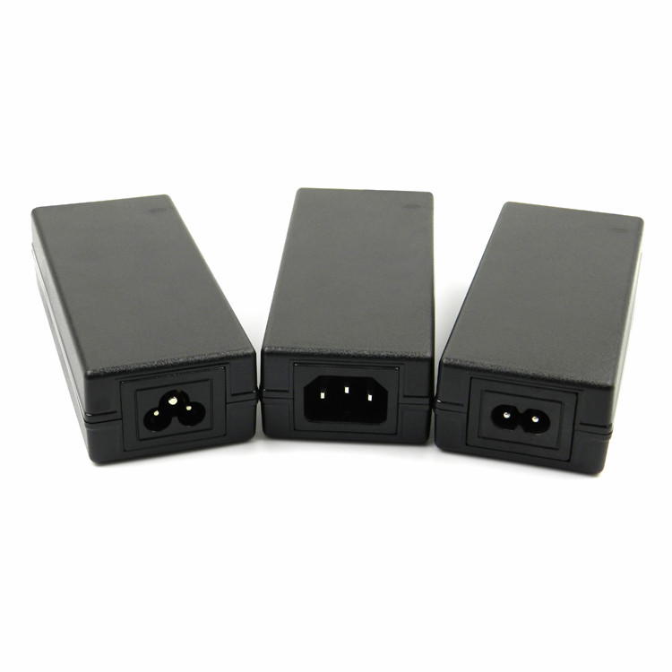
The KSPOWER brand 12.6VDC for 3S Battery Charger is one black or white color, accepts universal input 100-240V AC voltage and provides the complete power transformer solutions covering the dc output wattages ranging from 5 watts to 100 watts and the output current ranging from 100ma to 8000ma single output chargers. The 12.6V class 2 battery charger features high energy efficiency level VI and reliability, with quick charging function used for 18650 batteries and li-ion batteries, etc. The battery charger cell adopts constant voltage and constant current mode and accepts wall plug-in version, desktop version, and cord to cord version, all available with 2 colors LED indicator for charging status(Green and Red light). The li-ion battery charger solutions also includes class I and class II installations, equipped with three standard AC inlets (IEC320-C14, IEC320-C6, IEC320-C8) and different kinds of AC plugs options.
12v dc charger,Wall Battery Charger,3s battery charger,12v battery charger,battery car charger Shenzhenshi Zhenhuan Electronic Co., Ltd , https://www.szzhpower.com