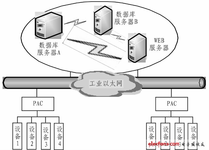
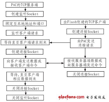
Abstract: According to the shortcomings of the current Web-based remote industrial monitoring program, the use of Flash is highly interactive, and the exported file itself is small, suitable for network transmission, and the use of AS (AcTION Script) to improve the interactivity with other languages. Design idea of ​​remote industrial monitoring system of flash. The four-layer architecture of the system is proposed, and based on the four-layer architecture, a detailed hardware connection design and system software design are carried out for the system. The core idea of ​​the system is to use Socket to realize data communication between Flash client and server, and RemoteObiect to store historical data. The design of this system provides a new idea for remote industrial monitoring based on Web and has practical application value. At present, the products in the monitoring field generally pay attention to the field level, that is, the client / server (C / S) mode is adopted, and its purpose is to ensure the stability and reliability of the monitoring system. However, with the continuous development of computer technology, network technology and control technology, at the same time, in order to fully integrate fieldbus, enterprise information network and external Internet, and improve the level of enterprise automation and equipment maintenance and management, network-based Web remote monitoring Will be widely used in the future monitoring system. 1 Current situation analysis At present, there are generally three kinds of Web-based remote industrial monitoring solutions: 1) Store the data collected by OPC or other communication methods into the database through intermediate software, and then interact with the database through the Web page to achieve the purpose of device monitoring: 2) Embedding into a web browser by plug-in to achieve interaction with the controller; 3) Interacting with the controller through the Web service, that is, sending the control interface and data information of the device through the deployment of the Web service, monitoring center Discover and call these web service methods through the network to complete the control and data collection of field devices. In the first scheme, the intermediate process is too complicated, which violates the principle of stability and reliability of the monitoring system. There are many limiting factors in the intermediate link, and it is not easy to control. The monitoring delay is also very obvious, and the timeliness is insufficient; second In this solution, the control of the developed monitoring device is inserted into the web page, and the security of the browser needs to be reduced. At the same time, the control must be downloaded in advance for each monitored host before use, and such controls and other web browsers The functional integration of the Web page and the display effect of the monitoring page are poor, and it is difficult to achieve the rich display effect in the B / S mode; the third solution, the transmission of the non-real-time connection through the Web service, must be through the loop Continuously refreshing the data will not only increase the burden on the device, but will also have a fixed delay problem. Therefore, based on the deficiencies of the above monitoring schemes, a remote monitoring system implementation scheme based on Flash is proposed. The program uses Flash with strong interactivity, and the exported file itself is small, suitable for network transmission. Using AS to improve the interactivity with other languages ​​and other characteristics will greatly improve the deficiencies of the above three programs, making Web-based remote monitoring The system has greatly improved the reliability, stability, timeliness, compatibility with the Web, page display effects and user interaction experience. 2 Based on Flash remote industrial monitoring system architecture The architecture of the Flash-based remote monitoring system can be divided into four layers: detection and control of field devices, Web publishing system, client data reception and command sending, and data storage and forwarding. On the one hand, on-site equipment detection and control is responsible for collecting the operating data of each control node on the site, and passing it to the middle-tier subsystem after aggregation and preprocessing; on the other hand, it receives the control commands forwarded by the middle-tier subsystem, and analyzes and verifies the commands , And then instruct each control node on site to take corresponding actions. The Web publishing system is mainly provided by the Web server to provide Web services to achieve the release of the client. The Web server is the intermediate link to complete the interaction with the client subsystem and the field subsystem. The customer subsystem is the part that interacts directly with the user. It receives user input, obtains monitoring data from the field device detection and control subsystem, or sends commands to it. The data storage and forwarding system is mainly composed of a database server and services that provide Web services, and the database server completes the storage function of collected data. Through the role of these four processes to achieve remote monitoring of equipment. Its architecture is shown in Figure 1. Figure 1 Flash-based remote device monitoring system architecture 3 Design based on Flash remote monitoring system 3.1 System hardware connection design The field device communicates with the data collection module through the serial port, the data collection module is connected with the Web server through industrial Ethernet, and the Web server is connected with the database server through Ethernet. The data acquisition module uses PAC (Programmable Automation Controller) and supports Modbus / TEP communication protocol. The Web server and the database server use HP servers, and the operating system installed is Windows Server 2008 Enterprise. The network topology uses a star topology, in order to be able to establish a more effective connection with the field collection equipment. The Web server stores data directly facing the database server, which is easy to reduce the burden on the entire network and prevent network congestion caused by excessive data volume. At the same time, the database server implements dual-machine hot backup to improve the reliability of the system. The database is divided into two parts: a central database and an enterprise-level database. The central database mainly stores current data, and the enterprise-level database stores historical data and management data of devices and users to isolate dynamic data from static data. The network topology diagram is shown in Figure 2. Figure 2 overall system diagram 3.2 System software design The core content of software design is PAC programming and client Flash programming. The PAC programming language is C, the editing environment is BC compiler, the Flash programming language is AcTIon Script, and the editing environment is Flash builder4.5. This system realizes data transmission between PAC server and Web-based Flash client by creating a Socket established by TCP data stream. The process of establishing communication is as follows: First, the PAC server monitors its own Modbus / TCP dedicated port 502 through the Socket, and the client program uses this port and the IP address of the PAC server as connection Socket parameters to create a Socket to establish a connection with the PAC server. If the network is not faulty, the connection is established. The client sends and receives information through the SendMessage () and ReadBytes () methods of Socket in Flash. The Modbus / TCP socket model based on Flash created as shown in Figure 3. Figure 3 Modbus / TCP socket model 3.2.1 1PAC server program implementation The realization of the PAC server is mainly divided into two parts: the communication with the host computer through the Socket and the communication with the peripheral equipment through the serial port service. The communication with the host computer through Socket is mainly divided into monitoring and connection. In the listening state, it is responsible for monitoring the client's request connection and accepting this connection. The PAC side of this system is designed with the ServerListen listening class. The listening class first binds the local port 502 through int bind (int sockfd, struct sockaddr * my_addr, int addrten), and then uses the function int listen (int sockfd, intbacklog) to The connection request is put in the queue and waits until the function intaccept (int sockfd, void * addr, int * addrlen) processes it, and then returns a brand new socket file to describe this single connection. In this way, there are two file descriptors for the same connection. The original file descriptor is listening on the port you specified. The new file descriptor can be used to call send () and recv (). In the connection state, it is responsible for receiving and sending data with the client, through the data transmission class Server Custom. In this class, use the int send (SOCKETs, const char FAR * buf, int len, int flags) function to send the data of the PAC server to the client. If the network fails or the length of the data to be sent len ​​is less than the current program to send data The length of the buffer area returns SOCKET_ERROR, using int recv (SOCKETs, char FAR * buf, int len, int flags) to receive data from the client. The function first waits for the data in the send buffer of s to be transferred by the protocol. If the network error occurs when the protocol transmits the data in the send buffer of s, the function returns a SOCKET_ERROR error. If there is no data in the send buffer of s or the data is successful After sending, the function first checks the receive buffer of socket s. If there is no data in the receive buffer of s or the protocol is receiving data, the function waits until the data is received by the protocol. The communication for peripheral devices is mainly through the serial port service, first call the COM port initialization function InstallCom defined by yourself to initialize the port, and then use the build_REQ_Read function to implement the data of the peripheral device read by the COM port into a custom array according to the ModBusRtu communication protocol , And CRC check through CRC16_modbus. If the received data is correct, analyze the data read from the serial port through analyze_Read_Result, and store the read data bits in the Share_Mem [MaxShareMemNum] array. Then use the Share_Mem array as the REMOTCP_ModServer_Create parameter to communicate with the host computer. To send a command to a peripheral device, after selecting the COM of the control object through the function SendCommand, the command is sent to the peripheral device, and the peripheral device acts after receiving the command. French type 16A 250V~, IP20, Class I, non-rewirable, single-way socket outlet complies ,with shutter, with a non-rewirable plug, with cord H05VV-F 3G1,0-1,5mm 2 (max length be 2m for 1,0mm 2 and 30m for 1,5mm2 ). French Extension Cord,Extension Cord With Usb,Power Extension Cord,Outdoor Extension Cord CIXI KYFEN ELECTRONICS CO.,LTD, , https://www.kyfengroup.com


16A 250V~, IP20, Class II, non-rewirable, with single way socket-outlet with shutter, with a non-rewirable plug, with flexible cord H05VV-F (with or without fabric braided cover) 2G1,0-1,5mm 2 (Max. 2m for 1,0mm 2 in length and Max.30m for 1,5mm 2 ).