Abstract: A wireless feedback full-bridge non-contact electric vehicle charging circuit is presented. The primary coil of the non-contact charging circuit transfers electrical energy to the secondary coil on the chassis of the electric vehicle. The wireless feedback circuit wirelessly feeds back the sampling signal of the load voltage to the control end of the primary circuit in the non-contact charging circuit, and automatically adjusts the duty cycle of the primary circuit full-bridge converter to stabilize the output power at the set value. In addition, the circuit also has intelligent detection of battery power, automatic charging, floating charge and stop charging. Simulation and experiment prove the feasibility of the circuit. This article refers to the address: http:// Pod E-cigarette Shenzhen Yingyuan Technology Co.,ltd , https://www.smartpuffvape.com
Keywords: electric vehicle; contactless power supply; wireless feedback
1 Introduction The Inductively Coupled Power Transfer (ICFT) used in electric vehicles transmits electromagnetic energy to the primary coil to the secondary coil. The secondary coil is mounted on the chassis of the vehicle, and the primary coil is installed under the ground of the parking space. When the electric vehicle is docked to the power supply coil device with a fixed parking space, the power receiving coil can receive electric energy and charge the battery. Generally, electric vehicles can be charged within 3 to 6 hours.
Compared with the wired charging method, the non-contact charging system has intelligent charging, and does not require a dedicated person to be on charge of the charging site; charging is not affected by weather and environment. Experiments show that the coupling coefficient of the non-contact charging system is low, usually between 0.13 and 0.2, and the voltage fluctuations at both ends of the load are large. Here is a non-contact power supply circuit with wireless feedback voltage regulation function. Under the premise of not changing the coupling coefficient, the duty ratio of the H-bridge of the non-contact power supply circuit is adjusted, and the output power of the primary circuit is changed to achieve the purpose of stabilizing the output voltage. .
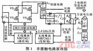
2 Non-contact power supply circuit principle The schematic diagram of the non-contact circuit is shown in Figure 1. The circuit includes a contactless power supply circuit and a wireless feedback circuit. The contactless power supply circuit includes a primary circuit and a secondary circuit; the wireless feedback circuit includes a detection and transmission circuit and a receiving and feedback trigger circuit, which can simultaneously implement intelligent control and voltage stabilization functions. 
In Figure 1, the primary circuit consists of power switch tubes VS1 ~ VS4 to form a full-bridge converter circuit, using PWM control chip SG3525 to control the push-pull circuit to generate control pulses, respectively, alternately control the gates of VS1, VS4 and VS2, VS3, so that L11 two The terminal generates an alternating current with a frequency set to 30 kHz.
L11, L12 constitute a non-contact coupled converter. C1, C4 are the compensation capacitors of the primary and secondary coils, the primary power supply, the primary converter and the primary coil L31 are installed under the ground; the secondary coil L12 and the secondary converter are installed in the chassis of the vehicle. Electrical isolation between primary and secondary.
VD1, VD2 and C2, C3 form a double voltage rectification circuit, which is filtered by L2 and C5 to supply power to the load.
In the equivalent circuit of Figure 1, the previous circuit of the H-bridge of the full-bridge converter can be regarded as a square wave voltage source, and its internal resistance RS is mainly the equivalent internal resistance of the power grid meter. It can be seen that the necessary condition for obtaining the maximum transmission power of the RL is to make the primary and secondary circuits in a resonant state. According to this rule, by theoretical calculation and Pspice simulation, L11=10μH, L12=112μH, C1=1 nF and C4=0.1 nF are obtained.
3 wireless feedback regulator and communication circuit principle
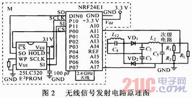
3.1 Wireless signal transmission circuit The wireless signal transmission circuit is shown in Figure 2. The circuit is composed of a wireless transmitting module NRF24E1 containing a single chip microcomputer and peripheral circuits. R1 and R2 form a resistor divider circuit. The sampled voltage signal at both ends of R2 is sent to the analog input terminal AIO of NRF24E1. This port has an A/D conversion function, and the converted digital signal is transmitted to the receiving circuit. When the load voltage is set at 24 V, the sampling voltage signal amplitude is set to 1 V by accurately selecting the ratio of R1 and R2. 
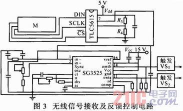
3.2 Wireless signal receiving and feedback trigger circuit Figure 3 is the wireless signal receiving and feedback control circuit. It is set by software to receive signals. After the wireless module receives the digital signal. The chip TLC5615 is used to implement D/A serial conversion, which converts the digital signal into an analog signal of about 1V and is output by the 7th pin. Send this analog voltage signal to pin 1 of the SG3525 (inverting input of the error amplifier). The 16-pin of the SG3525 is a 5.1 V reference voltage, which is accurately divided by a resistor, so that the 2 pin (non-inverting input) of the SG3525 receives a standard 1 V voltage signal. The SG3525 automatically changes the difference between the voltage signals of pins 1 and 2 by real-time.
11.14 The duty cycle of the output pulse of the pin, control VS1 ~ VS4, change its duty cycle, thereby adjusting the power transmitted to the secondary circuit, for the purpose of voltage regulation. 
In addition, the circuit also has intelligent judgment and automatic processing functions: when the car is not in the parking space, the signal receiving circuit does not receive the signal, the non-contact power supply primary circuit is automatically turned off, thereby saving energy; automatically determining the battery by detecting the load voltage The degree of charge is automatically switched to the floating charge and the charge down state.
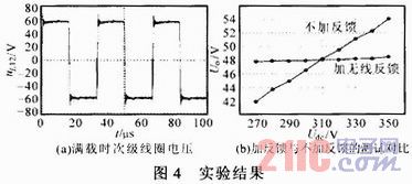
4 Experimental results and conclusions Designed input DC voltage Udc=310 V (obtained by mains rectification), output DC voltage Uo=48 V electric vehicle non-contact charging circuit, working frequency fs=30 kHz, load 1 kVA, 48 V Special battery for electric vehicles. The experimental results are shown in Figure 4. 
As can be seen from FIG. 4b, the wireless feedback non-contact charging circuit has a better voltage regulation effect. Through the magnetic field coupling simulation and experiment, when the primary and secondary coils are separated by 10 cm, the inductive coupling coefficient is 0.15. The critical components (L11, L12, C1, C4) specifications are precisely selected to make the circuit in a better state.
In addition to the voltage regulation function, the circuit also has intelligent charging, under-voltage and over-current protection. When the load is short-circuited, the voltage across the secondary coil automatically approaches zero, which acts as an automatic protection.