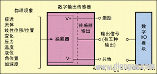
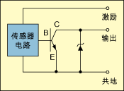
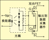
Digital sensors and actuators driven by digital signals are widely used, and digital sensors can be found in almost all real-world variables such as temperature, flow, pressure, speed, etc., and their digital outputs are available in a variety of formats. This article first classifies digital sensors based on the type of output signal and circuit interface, and then points out which issues to be aware of when selecting a digital I/O module that interfaces with the sensor. Digital sensors are different from analog sensors. The output value of the analog sensor is a value that varies continuously over the entire output range. The output value of the digital sensor is only two types. It is not “0†or “1â€. Touch switch One of the simplest examples of digital sensors, when not pressed, the tact switch is usually an open circuit with an infinite impedance, and when pressed, it becomes a short circuit with zero impedance. When docking a digital sensor to a data capture device, you must consider some of the key factors that can affect the performance of the interface. Below, we'll cover these key factors and give you an easy way to guide you to the right data capture device for your application. Classification of digital sensors Due to technological advances, a variety of complex digital sensors have emerged on the market, and today's sensors have been able to generate a long series of switching state transitions. With these sensors, the frequency characteristics of the output pulse train, even the pulse shape, can Characterize the measurement results of the sensor, making continuous measurement possible. Figure 1 classifies the sensor according to the signal characteristics of the drive signal output by the sensor (there are 5 types). Among them, 45% of the digital sensors represent the output of the digital line, and 35% represent the output signal frequency, 12%. The output is characterized by the duty cycle of the output signal, with 6% being characterized by time intervals and 2% being characterized by the number of pulses. The signal characteristics that can express sensor measurements are the first selection parameters to consider when selecting the industrial digital blocks required to capture sensor data. This parameter is important when deciding whether a counter is needed in the digital I/O module you choose. The terms suction and pumping define the flow direction control of the DC current in the load. The sink device provides a path to ground for current and is not responsible for powering the device. Devices containing the terms NPN, open collector, and IEC negative logic are all inhaled devices. The pump-out device provides power or a positive voltage to sink current into the load. Devices with names such as PNP, Open Emitter, Normally Low, and IEC Positive Logic are all pump-out devices. The concepts of suction and pumping are independent of the components used to perform the operation (whether the component is a transistor, mechanical relay, or others). This concept is applicable to any DC circuit, but the components used to implement this circuit can have a variety of options. 2-wire sensor or 3-wire sensor It is important to define the relationship between current and voltage when the sensor is on and off. A sensor can be classified as a 2-wire sensor or a 3-wire sensor in the following manner. 2-wire sensor This sensor is connected in series with the data capture device. When the sensor is not activated, it only absorbs a minimum operating current. This current value is equal to the off-state leakage current of the sensor. Some sensor manufacturers also call it residual current. When the sensor is not connected to the data capture device and is directly connected to other loads, there is no residual current problem. For example, in industrial environments, these 2-wire sensors are often directly connected to the motor and low-resistance devices like motors. But if the residual current required by the sensor is higher than the current that the digital I/O module can provide, then the problem arises. At this point, the digital I/O module may erroneously detect the off state as being on because the current drawn by the sensor is higher than the current it is intended to provide. Most 2-wire sensors in industrial applications have an off-state leakage current or residual current no higher than 1.7 mA. Similar to the off state, the sensor needs a minimum current to maintain the on state. This is the minimum holding current, which is usually between 3 mA and 20 mA. If the digital I/O module is unable to sink or supply this current, the sensor will not function properly. The 3-wire sensor does not draw energy directly through the digital output line, but instead draws energy from an excitation terminal. Some manufacturers also call this sensor a line-driven sensor. The current that this type of sensor absorbs from the digital I/O module is called the load current and is typically around 20 mA. Note, however, that this current is provided by the excitation terminal. Digital sensor drive circuit Classification by electronic components that implement sensor output. There are three types of electronic components used to drive digital sensor outputs: mechanical relays, transistors, and bidirectional FET devices. A mechanical relay is an electromagnetic device that can be turned on when the contact is closed and can be cut off when the contact is opened. This device is capable of withstanding current loads at high voltages. Mechanical relays are low-speed devices relative to solid state relays and are therefore commonly used in sensors that characterize output in line conditions. A common problem with such devices is contact aging and increased impedance, and the life of the contacts depends on the current load and operating frequency. When connected to a counter or digital I/O module, the mechanical relay sometimes outputs an indeterminate result due to the contact bounce. A transistor is a solid-state device used to control DC current. There are two types: NPN type and PNP type, which are commonly used as output switches in sensors with low DC power supplies. Figure 2 shows an NPN (current absorbing) type open collector transistor. The bidirectional FET device is implemented in a structure called a bidirectional FET output, as shown in Figure 3. This structure has many advantages, but the most important is that it can directly interface with TTL and CMOS circuits, and it has the characteristics of low off-state leakage current and fast response. FET means a field effect transistor, which is the most suitable device for use as a digital sensor output because its operating characteristics are close to the ideal model. Digital sensor I/O module selection When choosing a digital I/O module, we must answer the following three questions: 1. What characteristics of the digital signal output by the sensor can characterize the measurement results of the sensor? From Listing 1, you can select a set of digital I/O modules. 2. Is the output of the sensor a suction output or a pump output? Table 1 also provides a set of NI digital I/O boards that are classified according to their inhalation and pumping capabilities. If the sensor you are using is a suction output, you will need to select a pump-out input I/O board. vice versa. 3. What components are used to achieve sensor output? At this point we may need to consider the sensor's off-state leakage current and the on-state minimum holding current. By comparing the specifications of the sensors in Table 2 with the specifications of the data capture device, you can select the digital I/O device that best fits your sensor. In the selection process, in addition to considering the voltage, the following two conditions must also be taken seriously (sometimes we will ignore it): 1. The off-state leakage current of the sensor ≤ the low-state maximum input current of the I/O board; 2. The minimum holding current of the sensor ≤ the high state maximum input current of the I/O board. Transparent Led Film Screen,Adhesive Transparent Led Display,Adhesive Led Transparent Film Screen,Transparent Led Display Film Screen Guangdong Rayee Optoelectronic Technology Co.,Ltd. , https://www.rayeeled.com

