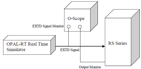
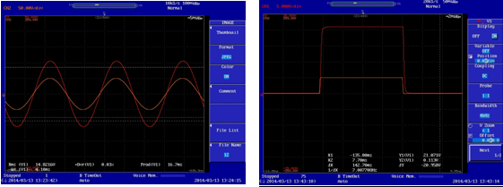
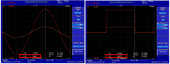
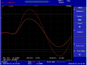
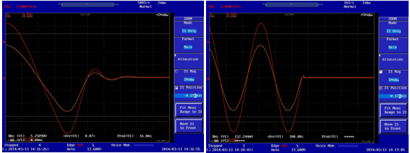
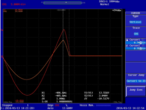
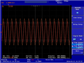
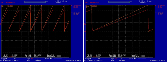
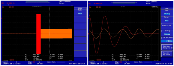
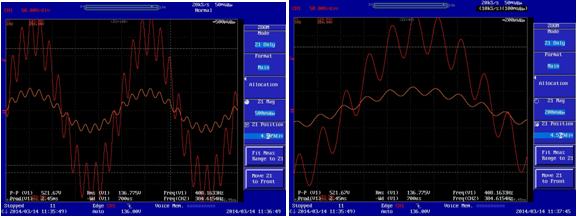
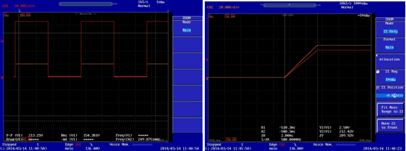
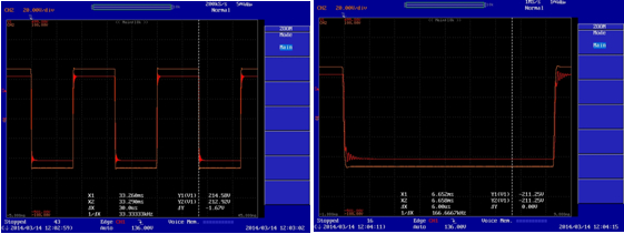
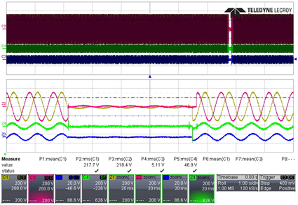
In the research project of smart grid, it is one of the key research topics to allocate power supply from different sources in real time to meet the energy demand of the current microgrid. As an important means of research, a complete set of simulation systems is built in the laboratory, including wind energy, solar energy, energy storage batteries, electric vehicles (charging piles), power motor equipment, conventional loads (such as home appliances), etc. Various simulators and even real-world facilities are all connected together through a controlled grid simulator to study the performance of various power sources and electrical loads in various situations. For such a complete test platform, the grid simulator is the core connection device of all other devices. By adjusting its output, it can easily simulate various incidents or harmful events on the real power grid, and observe and judge the response of various mounted devices. Behave in order to make corresponding improvements. This requires the grid simulator to have powerful voltage and frequency regulation control capabilities, good support for two-way flow of energy, and flexible external control of external command control. Especially with the deepening of research, the real-time requirements for controlling the output of the analog grid are getting higher and higher, and the waveform changes are becoming more and more complex. It is required to realize the so-called hardware-in-the-loop simulation, which is for ordinary communication. The requirements for the control capabilities of the source grid simulator products are also becoming more stringent. The conventional control method is panel operation or remote program control by sending SCPI commands through communication interfaces such as GPIB/RS232/USB/Ethernet, but these two methods are difficult to meet the current requirements for complex waveform output in real time. The real-time better control method is to directly control the output of the grid simulator by using an external analog signal. At this time, the working state of the grid simulator is equivalent to a linear amplifier, and the external analog signal is directly scaled up. And provide corresponding output power support. As for the source of external control signals, especially the simulation capabilities that will require various complex conditions, there are also mature commercial tools, Real TIme Digital Simula TIon (RTDS). RTDS is a powerful tool that combines hardware and software. It has a wide database of power system component modules built in. Users can use the existing component modules to build the circuit of the power system and set the corresponding research sequence in the graphical software interface. RTDS continuously produces output to truly represent the situation in the real network, simulating many harsh but realistic situations, providing a large number of digital and analog input and output interfaces that can be directly connected to external device devices. We use the RS series high-power AC source from AMETEK California Instrument (CI) as the grid simulator for the RTDS. This product can provide 90KVA to 1MVA power output and support 100% of the nominal power. Bidirectional flow, stable output frequency range of 16Hz to 820Hz, also supports DC output. The external analog control interface currently provides support for 0 to 7Vac input voltages corresponding to 0 to full-scale output voltage, and supports three-phase independent control of their respective analog inputs. We use this RS AC power supply to complement a Canadian brand real-time controller to verify system performance. The system test configuration scheme is as follows. It should be noted that the CI RS power supply itself is a switch mode power supply, and its ability to regulate the output change has an inherent upper limit. In normal operation, the controller of the power supply itself can distinguish the control signal and can actively reject the over-limit operation. Execution, for example, we cannot set the frequency or voltage value beyond the allowable range for the power supply. When we use external analog signal control, in order to achieve better real-time performance, the external signal is a power module that directly controls the CI RS power supply, without prior judgment by its controller. Therefore, the hardware design must take into account the situation where the input signal is over-limit or is superimposed with more interference signals, which cannot cause damage to the power supply. The CI RS power supply deliberately adds a filter to the input of the external analog signal to filter out high-frequency clutter interference. In addition, the corresponding protection measures are taken for the control signal beyond the capability of the power supply itself. The verification process of the system function is as follows. (1) The case of ordinary 60Hz sine wave and square wave. Preliminary waveform verification proves that the CI RS power supply can basically provide the output in accordance with the signal of the real-time controller. The following are the cases where the control signal is a 60 Hz sine wave and a square wave. The orange waveform is the voltage signal of the real-time controller, and the red waveform is the RS output voltage waveform. Using the oscilloscope's waveforms, we can easily verify what the delay is when the CI RS supply accepts external analog control. From the measured results, it is basically around 100 microseconds. (2) The 60Hz sine wave starts from 0V to 230V. (3) The case where the 60 Hz sine wave is turned off from the 230V gradient (left) and directly turned off (right). (4) The 60 Hz sine wave is turned off with a 1 ms gradient from a 230 V 90 degree angle. (5) The case of 800 Hz output. At present, the upper limit of the signal frequency of the CI RS receiving external analog control is 819 Hz, and the upper limit of the frequency is 500 Hz when the reverse irrigation function is turned on. When this limit is exceeded, the RS automatically cuts off the output for protection. The following is the output performance when using an external analog to control 230V 800Hz. (6) The case of a 60 Hz 230V triangular wave. The picture on the right is an enlarged detail. (7) Performance of high frequency protection. When the CI RS is controlled by the external analog quantity to output the upper limit frequency, the RS automatically turns off the output after about 150ms. The picture on the right is a detailed view of the zoomed off moment. (8) Performance after superposition of 400Hz peak-to-peak ripple noise on a 230V 60Hz sine wave. The picture on the right is an enlarged detail. (9) Performance of 215V low rising slope square wave (rise time is about 2 milliseconds). The picture on the right is an enlarged detail. good performance. (10) Performance of a 215V high rising slope square wave (rise time is approximately 30 microseconds). The picture on the right is an enlarged detail. It can be seen that when the external control signal requires the rate of change of the voltage of the CI RS to exceed its capability, the output of the CI RS will ring. (11) Simulation in the case of loading. Since CI RS itself acts as a voltage source, it mainly regulates the output voltage, and the current is determined by the load pull. The current output performance is independent of whether the control source is controlled by the local machine or external analog control. Numerous practical applications have proven that CI RS outputs excellent current performance under various voltage waveforms when using its own controller. The following is a waveform diagram of a grounding fault simulation using a CI RS to receive an RTDS control signal from a research institute in Korea, with a load of 30 kW + 10 KVA. The yellow track is the A phase voltage, the purple track is the B phase voltage, the green track is the A phase current, and the blue track is the RTDS control A phase voltage signal. Based on the above verification test results, the 100 microsecond delay is also an acceptable range, so we have an analog grid platform that can truly provide a power range from 90KVA to 1MVA. With RTDS system, it can realize various complex powers. The simulation of the environment, connecting various new energy power generation equipment, electricity load, energy storage equipment, etc., can establish a complete set of micro-grid simulation test platform in the laboratory to meet the needs of scientific research and practical verification. Filter Choke Inductor,power Filter Inductor,PCB mount Filter Inductor,UU Filter Inductor,UTFilter Inductor IHUA INDUSTRIES CO.,LTD. , https://www.ihua-transformer.com