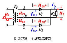
The full-wave rectifier circuit is shown in Figure Z0703. It consists of a secondary power tap Tr with center tap, two rectifier diodes D1, D2 and a load resistor RL Genuine Flip Cover Leather Case Genuine Flip Cover Leather Case,Cover Leather Case,Flip Cover Leather Case,Genuine Leather Case Guangzhou Jiaqi International Trade Co., Ltd , https://www.make-case.com . The transformer secondary voltages u21 and u22 are equal in magnitude and opposite in phase, ie
U21 = - u22 = ![]()
Where U2 is the rms value of the AC voltage of the secondary winding of the transformer.
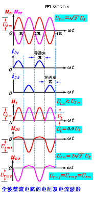
The working process of the full-wave rectification circuit is: in the positive half cycle of u2 (ωt = 0~π), D1 is positively biased, D2 is reverse biased, and RL is on  There is a top-down current flow, and the voltage on RL is the same as u21.
In the negative half cycle of u2 (ωt = π~2π), D1 is reverse biased off, D2 is positively biased, and there is also a top-down current flowing through RL.
The voltage on RL is the same as u22. The rectified waveform can be drawn as shown in Figure Z0704. It can be seen that the load is also a one-way pulsating current and a pulsating voltage. The average values ​​are: ![]()
![]() GS0705
GS0705
The average current flowing through the load is ![]() GS0706
GS0706
The average current (ie, forward current) flowing through diode D is 
The highest reverse voltage applied across the diode is 
When selecting a rectifier diode, the two parameters should be used as the limit parameter.
The DC component (more than half wave) of the full-wave rectified output voltage increases, and the pulsation degree decreases. However, the transformer needs a center tap and is troublesome to manufacture. The rectifying diode needs to withstand a high reverse voltage, so it is generally suitable for requiring the output voltage to be not too high. The occasion.
The full-wave rectifier circuit is shown in Figure Z0703. It consists of a secondary power tap Tr with center tap, two rectifier diodes D1, D2 and a load resistor RL  . The transformer secondary voltages u21 and u22 are equal in magnitude and opposite in phase, ie
U21 = - u22 = ![]()
Where U2 is the rms value of the AC voltage of the secondary winding of the transformer.
The working process of the full-wave rectification circuit is: in the positive half cycle of u2 (ωt = 0~π), D1 is positively biased, D2 is reverse biased, and RL is on  There is a top-down current flow, and the voltage on RL is the same as u21.
In the negative half cycle of u2 (ωt = π~2π), D1 is reverse biased off, D2 is positively biased, and there is also a top-down current flowing through RL.
The voltage on RL is the same as u22. The rectified waveform can be drawn as shown in Figure Z0704. It can be seen that the load is also a one-way pulsating current and a pulsating voltage. The average values ​​are: ![]()
![]() GS0705
GS0705
The average current flowing through the load is ![]() GS0706
GS0706
The average current (ie, forward current) flowing through diode D is 
The highest reverse voltage applied across the diode is 
When selecting a rectifier diode, the two parameters should be used as the limit parameter.
The DC component (more than half wave) of the full-wave rectified output voltage increases, and the pulsation degree decreases. However, the transformer needs a center tap and is troublesome to manufacture. The rectifying diode needs to withstand a high reverse voltage, so it is generally suitable for requiring the output voltage to be not too high. The occasion.