So-called electromagnetic interference, in a broad sense, all non-useful signals entering the channel or communication system are called electromagnetic interference. Electromagnetic interference has penetrated into our daily lives. For example, when watching TV, some people nearby use electric drills, hair dryers and other electrical appliances, which will make the TV screen appear snowy, the sound of the sound in the sounder... and so on. People of this type have long been commonplace and used to it, but the harm of electromagnetic interference is far more than that. In fact, electromagnetic interference has caused civil aviation system failure, poor communication, computer operation errors, malfunction of self-controlled equipment, and even endangering personal safety. Therefore, how to effectively suppress electromagnetic interference has become a factor that analog engineers must have and consider. Here, we will elaborate on what is electromagnetic interference and how to effectively suppress electromagnetic interference. Analysis of electronic circuits and electromagnetic interference Modern electronic products are becoming more and more powerful, and electronic circuits are becoming more and more complex. Electromagnetic interference (EMI) and electromagnetic compatibility issues have become major problems, and circuit design has become more and more demanding for designers. Electromagnetic interference is generally divided into two types, conducted interference and radiated interference. Conducted interference refers to the coupling (interference) of signals on one electrical network to another electrical network through a conductive medium. Radiated interference refers to an interference source that couples (interferes) its signal to another electrical network through space. Therefore, the research on EMC problem is the study of the relationship between interference source, coupling path and sensitive equipment. In 1990, the US Federal Communications Commission introduced regulations on commercial digital products in 1992, which required companies to ensure that their products meet strict susceptibility and emission criteria. Products that comply with these regulations are said to be electromagnetically compatible. At present, EMC has basically set up corresponding market access certifications in various regions of the world to protect the electromagnetic environment of the region and the competitive advantages of local products. Such as: North American FCC, NEBC certification, EU CE certification, Japan's VCCEI certification, Australia's C-TIck certificate, Taiwan's BSMI certification, China's 3C certification are all "passports" to enter these markets. Electromagnetic induction and electromagnetic interference Many people are engaged in the design of electronic circuits, starting with the understanding of electronic components, but the electromagnetic compatibility design should actually start from the electromagnetic field theory, that is, from the electromagnetic induction. The general electronic circuit is composed of resistors, capacitors, inductors, transformers, active devices and wires. When there is voltage in the circuit, an electric field is generated around all the charged components. When there is current flowing in the circuit. At the time, there is a magnetic field around all the carrier fluids. The capacitor is the most concentrated component of the electric field. The current flowing through the capacitor is the displacement current. This displacement current is caused by the two plates of the capacitor being charged and generating an electric field between the two plates. Charge and discharge are generated to form a displacement current. In fact, the current in the capacitor circuit does not actually flow through the capacitor, but only charges and discharges the capacitor. When the two plates of the capacitor are opened, the two plates can be regarded as a set of electric field radiating antennas, and the circuit between the two plates will induce an electric field between the plates. The circuit between the two plates, whether it is a closed loop or an open circuit, generates a displacement current in the conductor that is in the same direction as the electric field (when the direction of the electric field changes constantly), that is, the current runs forward for a while, and then runs backward. The electric field strength is defined as the potential gradient, that is, the ratio of the potential difference to the distance between two points. A wire that is several meters long, when it flows through a few amperes of current, the voltage across it is at most a few tenths of volts, that is, the electric field strength of several tens of millivolts per meter, which can generate several amps of current in the conductor. It can be seen that the electric field has a great effect and its interference ability is strong. Inductors and transformers are the most concentrated components of the magnetic field. The current flowing through the secondary winding of the transformer is the induced current. This induced current is generated by magnetic induction when a current flows through the primary coil of the transformer. The circuit around the inductor and the transformer can be regarded as an induction coil of a transformer. When the magnetic flux generated by the leakage inductance of the inductor and the transformer passes through a certain circuit, the circuit acts as a "secondary coil" of the transformer. Induced current. Two adjacent loop circuits can also be regarded as one of the "primary coils" of the transformer, and the other loop can be regarded as the "secondary coil" of the transformer, so two adjacent loops are also produced. Electromagnetic induction, that is, mutual interference. As long as an electric field or a magnetic field exists in the electronic circuit, electromagnetic interference occurs. In high-speed PCB and system design, high-frequency signal lines, integrated circuit pins, various types of connectors, etc. may become radiation interference sources with antenna characteristics, can emit electromagnetic waves and affect other systems or other subsystems in the system. normal work. Open Frame For Infrared Touch Monitor
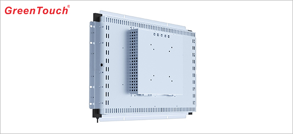
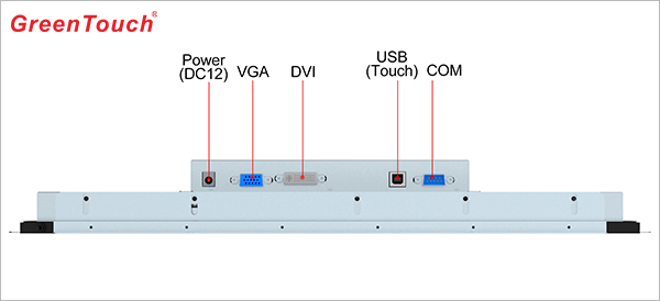
GreenTouch's LCD open frame for infrared Touch Monitor is a touch solution developed for automated information systems, gaming and entertainment, as well as light industrial automation controls,making GreenTouch's touch monitor product line even more complete.The touch monitor display is based on the concept "Design for simple and convenience", with proven GreenTouch expertise and reliability.GreenTouch's open frame touch monitor delivers an perfect solution that is cost-effective for worldwide customers requiring a reliable product .Designed with reliability from the start, GreenTouch's open frames deliver outstanding image clarity and light transmission with stable, drift-free operation for accurate touch responses.
* Display Type: Active Matrix TFT LCD, LED Backlight
Dust-Proof Industrial Touch Monitor,Waterproof Industrial Touch Monitor,Anti-Interference Touch Monitor,Wall-Mounted Embedded Touch Monitor,Infrared Touchscreen Monitors HuiZhou GreenTouch Technology Co.,Ltd , https://www.bbstouch.com
* Touch Type:Infrared ,10 Points Touch
* Display Ports:VGA+DVI,VGA+DVI+HDMI,VGA + DVI + HDMI + DP
* Touch Systems:Windows,Android,Linux
* Certificates:UL,FCC,CE,CB,HDMI
* Warranty:1 Year
* Customized:Support
