l Introduction Stepper motor has a big difference between the operation process and the general motor due to its special structure and operation mode. The operation theory is far less mature than the traditional motor, which brings a lot of inconvenience to the application of the stepping motor. Stepper Motor Operation Due to the complexity of the current and current waveforms, the calculation of current and operating torque often has to rely on the value method. The numerical method can simulate the specific stepping motor system and calculate the required results, but it is necessary to draw a general sense of regularity from it, and it must be supplemented by conceptual theoretical analysis. In this paper, the superposition principle is applied to divide the winding current of the stepping motor into two components, that is, the current component generated by the applied voltage and the current component generated by the rotational induced voltage. Correspondingly, the running torque is also divided into two corresponding components, and the torque component generated by the rotating induced voltage is further analyzed and experimentally studied. 2 Mathematical model The typical system of five-phase hybrid stepping motor with star-bridge drive is analyzed. The topology of the main circuit is shown in Figure 1. This is a system of five symmetrical structures. As long as the main circuit of one phase is analyzed, the other phases are similar. Take the A-phase circuit as an example: a. The forward loop of ia when TA is turned on. The positive terminal of the power supply passes through the TA to the A winding, and then passes through other reverse-conducting phase windings and corresponding power amplifier tubes to the negative terminal of the power supply.
Our Professional 100W solar panel manufacturer is located in China. including Solar Module. PV Solar Module, Silicon PV Solar Module, 100W solar panel for global market.
100W solar panel, Solar panel, PV solar panel, Silicon solar panel 100W Jiangxi Huayang New Energy Co.,Ltd , https://www.huayangenergy.com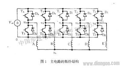 b. The forward loop of ia when TA is turned off. The forward current in the A winding passes through the other reverse-conducting phase windings and the corresponding power amplifier tubes, and then returns to the end of the A-phase winding through Dx to form a closed loop, as shown in FIG. 2 . c. The reverse loop of ia when Tx is turned on. The positive end of the power supply passes through other positive conduction power amplifier tubes and phase windings, to the A phase winding, and then through Tx to the negative end of the power supply.
 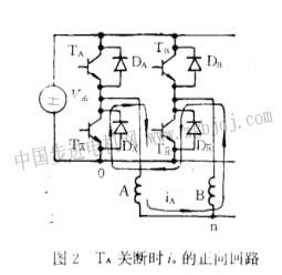 d. The reverse loop of ia when Tx is not conducting. The reverse current in the A winding forms a closed loop through the DA to other forward conduction power amplifier tubes and corresponding windings, as shown in Figure 3.
 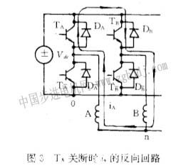 It can be seen that for any phase winding, regardless of whether the power amplifier tubes of the respective bridge arms are conducting and non-conducting, a loop of forward current or reverse current can be formed. In fact, the power amplifier tube only plays the role of controlling the voltage of the applied power amplifier stage, so that it can be forward, reverse or not applied to the winding of the corresponding phase. For any phase winding, the voltage equation is:
 Wherein the applied voltage V K --K-phase winding, and the main power amplifier is turned about the case, it is not a continuous function R- total flux linkage ψ K resistor current i K phase winding circuit eleven phase winding phase winding L jK is the self-inductance of the K-phase winding
  j≠K is the mutual inductance between the K-phase and the j-phase winding
  UθK - the rotational induced voltage of the K-phase winding
 ![]() Starting from the concept of superposition, equation (2) can be rewritten as:
Starting from the concept of superposition, equation (2) can be rewritten as: 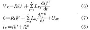 Accordingly, the electromagnetic torque can also be divided into two components, namely
  Where T (1) corresponds to i K (1) (K=a, b, c, d, e). If the influence of the rotational induced voltage on the winding current waveform is ignored, the resulting current and the corresponding electromagnetic are analyzed or calculated. Torque is this component, which is the basic component of electromagnetic torque. T (2) corresponds to i K (2) (K = a, b, c, d, e), which is a current component corresponding to the rotation induced voltage, which is determined by the equation (7). Starting from the theory and concept of ordinary synchronous motor, we know the law of the value of the torque component as a function of the rotational speed. It is the braking torque, which is equivalent to the internal electromagnetic damping. 3 Short-circuit torque torque component T (2) is determined by current component i K (2) , and i K (2) can be solved by equation (7). Equation (7) is actually a system of equations for short-circuit operation of the stator windings of the motor. For the sake of simplicity, the short-circuit operation analysis is carried out under the following assumptions: 1 The motor is operated at constant speed, ω = const. 2 The rotation induced voltage is a sinusoidal waveform. The self-inductance and mutual inductance of the 3-phase winding are constant. This is a symmetric steady-state operation, you can write out its phasor equation, and write a phase representation, for example, the equation for writing phase A is:
  It is known from the symmetry of the motor structure:
  From the symmetrical parts of the phase current (as shown in Figure 4):
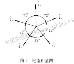
 Substituting equations (11)-(13) into equation (10), obtain the general expression of the phase winding voltage balance equation:
 ![]() The equivalent inductance of the Ls-phase winding
The equivalent inductance of the Ls-phase winding  I——phase current RMS U o ——phase winding rotation induced voltage RMS
  From equation (14), the short-circuit current is:
  The short circuit torque is:
  From another perspective, the electromagnetic torque of the motor can also be obtained from the winding current and torque coefficient. The electromagnetic torque generated by any phase winding current is:
  Total electromagnetic torque:
  Actually, the torque coefficient KT is equal to the rotational induced voltage coefficient Kt, so the time (18) is exactly the same as the equation (21). 4 Test The test motor is a 90BYG550A five-phase hybrid stepping motor. The torque test results of one phase winding when energized are shown in Figure 5.
 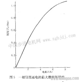 From the corresponding rated phase current (J-3A) on the curve, the holding torque is T K =0.6lNm, and the torque coefficient is:
  When the motor is open circuited and short-circuit tested, it is driven by a stepping motor of the same type. The control pulse frequency (fψ) of the driving motor is proportional to the speed of the motor under test and the frequency (f) of the rotating voltage. -5 energization mode, the number of rotor teeth Z r = 50, so:
  The measured value of the effective value of the open-circuit rotation induced voltage of one phase winding is shown in Fig. 6.
 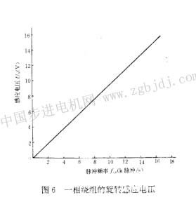 From any point on the curve, for example, corresponding to fcp = 10k pulse / s, Uo = 9.4V, the rotation induced voltage coefficient can be calculated as:
  When the short-circuit test is carried out at a higher frequency, the value of the short-circuit current is almost independent of the rotational speed, I = 0.96 A. The equivalent synchronous inductance of the phase winding is:
  The resistance of the phase winding is measured as:
  The above parameters are substituted (21, the relationship between the short-circuit braking electromagnetic torque and the speed or the control pulse frequency is:
  When fcp is small, T increases as fψ increases, which is proportional to:
 ![]() When f cp is very large, T decreases as fψ increases, which is inversely proportional to:
When f cp is very large, T decreases as fψ increases, which is inversely proportional to:  When the resistance of the phase winding is equal to the reactance, the value of the braking torque is the largest, and the corresponding frequency is:
 ![]() The maximum braking torque obtained by substituting (29) is:
The maximum braking torque obtained by substituting (29) is: ![]() The relationship between the short-circuit electromagnetic torque and the angular velocity (indicated by fcp) can be calculated according to equation (29), as shown by the curve in FIG. The × point in the figure is a measured result of the short-circuit braking torque. Since the measured torque also includes torque such as mechanical friction, it is reasonable to consider the calculated value of the electromagnetic torque slightly higher. When measuring the short-circuit torque, the motor under test is rotated by a DC motor, and the armature current of the DC motor is measured at different speeds. It is not difficult to determine the system of the motor under test if the torque coefficient is predetermined. Dynamic torque.
The relationship between the short-circuit electromagnetic torque and the angular velocity (indicated by fcp) can be calculated according to equation (29), as shown by the curve in FIG. The × point in the figure is a measured result of the short-circuit braking torque. Since the measured torque also includes torque such as mechanical friction, it is reasonable to consider the calculated value of the electromagnetic torque slightly higher. When measuring the short-circuit torque, the motor under test is rotated by a DC motor, and the armature current of the DC motor is measured at different speeds. It is not difficult to determine the system of the motor under test if the torque coefficient is predetermined. Dynamic torque. 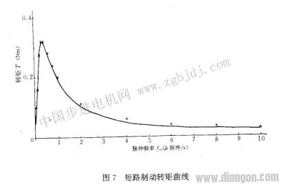 5 Conclusion In this paper, the running torque of the stepping motor is clearly divided into two components, which can deeply understand its running performance, control law and design law. In this paper, the typical five-phase hybrid stepping motor's star-bridge drive system is taken as an example to show that the control pulse signal only controls the applied power amplifier voltage. It cannot turn off the rotating induced voltage inside the system. The loop. That is, for the rotating voltage, it is equivalent to being short-circuited by the power amplifier bridge, and therefore, the effect of the rotating voltage is similar to the case where the power is short-circuited by the power supply in the ordinary synchronous motor. Analysis and example calculations show that the value of the braking torque component corresponding to the rotating voltage is larger in the low frequency band, which will have a more significant effect; his maximum value is less than ten percent of the holding torque. Twenty or so; in the high frequency band is small, almost no need to count. In synchronous machines, this torque component also exists, but a typical synchronous motor operates at a fixed frequency, and usually the synchronous motor (Xs) is much larger than the winding resistance (R), corresponding to the high frequency band, away from generating the maximum braking. The frequency of the torque, ie the braking torque, is not large and can often be ignored. The stepper motor is different. It operates in a wide frequency range and contains the frequency band that produces the maximum braking torque, which can have a non-negligible effect in a certain frequency band. The inference can be seen that there is a similar situation in the synchronous motor with variable frequency speed regulation.