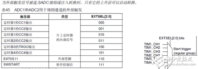
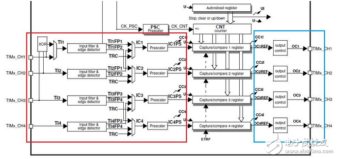
The ADC module is a 12-bit successive approximation analog-to-digital converter. It has up to 19 channels and can measure 16 external and 3 internal sources. The A/D conversion of each channel can be performed in a single, continuous, scan or discontinuous mode. The results of the ADC can be stored in a 16-bit data register in left or right alignment.    Key indicators of the ADC : the number of bits in the ADC module and the analog channel of the ADC module The number of bits in the ADC module: refers to the number of digits in the digital, which is closely related to the resolution. Analog channel of the ADC module: There are several analog acquisition intersections, which means how many analog quantities can be converted. The STM32's ADC has two modes, single conversion and continuous conversion. These two modes can be combined with the scan mode. CONT=0, SCAN=0 Single conversion mode (Single conversion mode) Single scan 1 channel CONT=1, SCAN=0 Continuous conversion mode (ConTInuous conversion mode) Continuous scanning 1 channel CONT=0, SCAN=1 Scan mode: All ADC_SQR sequence channels are switched once and stopped. (single scan group) CONT=1, SCAN=1 Scan mode: All ADC_SQR sequence channels are converted once and then cycled from the first channel. Continuously scan a group It should be noted that if more than one channel in your conversion sequence needs to be converted, then the scan mode must be enabled. Otherwise, only the first channel will always be converted. With ADC1, the order of the Regular channel is Ch0, Ch1, Ch2, Ch3, and the Scan mode is started. In single conversion mode: start ADC1, then 1. Start converting Ch0 2. Automatically start converting Ch1 after the conversion is completed. 3. Automatically start converting Ch2 after the conversion is completed. 4. Automatically start converting Ch3 after the conversion is completed. 5. Stop after the conversion is complete and wait for the next startup of the ADC. The next ADC startup starts from the first step In continuous conversion mode: Start ADC1, then 1. Start converting Ch0 2. Automatically start converting Ch1 after the conversion is completed. 3. Automatically start converting Ch2 after the conversion is completed. 4. Automatically start converting Ch3 after the conversion is completed. 5. Return to the first step after the conversion is complete If the Sacn mode is not activated, there are no steps 2, 3, and 4 in the above process. The above premise is that the DisconTInuous mode is not enabled. The regular channel of the STM32 ADC can be triggered by any of the above six signals. We use the TIM2_CH2 to trigger the ADC1. In stand-alone mode, only one channel is measured at a time. The ADC is configured as follows: (The following code uses the STM32 firmware library V3.5) Void ADC_ConfiguraTIon(void) { ADC_InitTypeDef ADC_InitStructure; ADC_InitStructure.ADC_Mode = ADC_Mode_Independent; ADC_InitStructure.ADC_ScanConvMode = DISABLE; //Close channel scan mode ADC_InitStructure.ADC_ContinuousConvMode = DISABLE; //Be careful not to use continuous conversion mode, otherwise it will be triggered once, and // subsequent conversion will never stop (unless CONT is cleared to 0), so the ADC after the first time is not from TIM2_CC2. Triggered ADC_InitStructure.ADC_ExternalTrigConv = ADC_ExternalTrigConv_T2_CC2;//Configure TIM2_CC2 as the trigger source ADC_InitStructure.ADC_DataAlign = ADC_DataAlign_Right; ADC_InitStructure.ADC_NbrOfChannel = 1; ADC_Init(ADC1, &ADC_InitStructure); RCC_ADCCLKConfig (RCC_PCLK2_Div6); / / configuration clock (12MHz), in the RCC should also be configured APB2 = AHB clock 72MHz, ADC_RegularChannelConfig(ADC1, ADC_Channel_8, 1, ADC_SampleTime_1Cycles5); ADC_Cmd(ADC1, ENABLE); ADC_ResetCalibration(ADC1); While(ADC_GetResetCalibrationStatus(ADC1)); ADC_StartCalibration(ADC1); //Start Calibration register While(ADC_GetCalibrationStatus(ADC1)); //waiting for finishing the calibration ADC_ExternalTrigConvCmd(ADC1, ENABLE); //Set the external trigger mode enable (this "external" is actually only the phase / / for the outside of the ADC module, actually inside the STM32) } Here again pay attention to the top sentence above the left picture: When the external trigger signal is selected as the ADC rule or injection conversion, only its rising edge can initiate the conversion. This has a lot to do with the correct configuration of Timer 2 below. Void TIM2_Configuration(void) { TIM_TimeBaseInitTypeDef TIM_TimeBaseStructure; TIM_OCInitTypeDef TIM_OCInitStructure; TIM_TimeBaseStructure.TIM_Period = 10000; / / set 100ms once TIM2 comparison cycle TIM_TimeBaseStructure.TIM_Prescaler = 719; / / system clocked at 72M, here divided by 720, equivalent to 100K timer 2 clock TIM_TimeBaseStructure.TIM_ClockDivision = 0x0; TIM_TimeBaseStructure.TIM_CounterMode = TIM_CounterMode_Up; TIM_TimeBaseInit(TIM2, & TIM_TimeBaseStructure); TIM_OCInitStructure.TIM_OCMode = TIM_OCMode_PWM1;//Detailed below TIM_OCInitStructure.TIM_OutputState = TIM_OutputState_Enable;//TIM_OutputState_Disable; TIM_OCInitStructure.TIM_Pulse = 5000; TIM_OCInitStructure.TIM_OCPolarity = TIM_OCPolarity_Low; / / If PWM1 is Low, PWM2 is High TIM_OC2Init(TIM2, & TIM_OCInitStructure); TIM_Cmd(TIM2, ENABLE); TIM_InternalClockConfig(TIM2); TIM_OC2PreloadConfig(TIM2, TIM_OCPreload_Enable); TIM_UpdateDisableConfig(TIM2, DISABLE); } At the top of the figure is the TIM2 auto-reload register and counter register. The following four Capture/compare x registers are TIM2_CCRx registers. To use the CC2 of TIM2 to trigger the ADC, it is critical to understand this diagram. First of all, it should be clear that the red and blue frames of this figure will not work at the same time. The red frame is configured to input capture mode to take effect. The blue frame is configured to output compare mode to take effect. TIM2_CCMR1_CC2S is configured to control TIM2_CC2. Which mode is in (CC2S=0 is the comparison output, 0 is the input capture), please note: one of the outputs of the blue box here is TIMx_CH2, and TIM2_CH2 is the trigger source of the ADC regular channel, that is to say if Triggering the ADC requires a rising edge on TIM2_CH2 each time a compare match is required. Then we first need to operate the leftmost part of the blue box, which is OC2REF. To make a rising edge occur when the comparison is matched, (taking the timer up count as an example), it is necessary to use TIM2_CNT "TIM2_CCR2, channel 2 is low. When TIM2_CNT>=TIM2_CCR2, channel 2 is high. As can be seen from the introduction of 0C2M[2:0] in the CCMR1 register of the Reference Manual Timer Section 4.7, only the PWM mode can satisfy the above conditions, any simple freeze, configuration OC2REF is high or low. Forcing OC2REF to be high or low, can not meet the requirements, many students are dead on this, thinking that it is configured TIMING mode, in fact, this can not change the level of OC2REF, there is no trigger ADC. CCMR1_CCxS (x is 1, 2, 3, 4, which channel is determined) is selected to capture input or compare output, here we need to configure as output. The above two configuration programs can drive AD conversion once in 100ms cycle, eliminating the need to use TIM and ADC interrupt resources.    To use the STM32 timer to trigger the ADC, the timer must be configured to compare the output PWM mode, and must pay attention to the rising edge of the TIMx_CHx output. If the comparison match occurs instead of the rising edge but the falling edge, then It is not necessary to trigger the ADC at the moment of a matching match, especially in applications similar to motor control. Portable Power Station also known as Portable Power Bank. Our product regulated DC Power, AC Pass-Through Charging, Wireless Fast Charger, Bluetooth Playback, Attentive Start, Car charger, Type-C ....... Large capacity meet the needs of all kinds of equipment. Portable Power Station,Indoor Portable Power Station,Solar Portable Power Station,Portable Power Station With Bms Jiangsu Zhitai New Energy Technology Co.,Ltd , https://www.zhitainewenergy.com
   The mission of the ADC is to convert continuously changing analog signals into discrete digital signals for computation, processing, storage, control, and display in our digital systems. 

Stm32 timer triggers adc
What is an ADC?