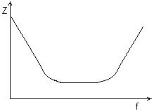
1. Principle and structure of the class capacitor 1.1 Supercapacitor structure Figure 1 shows the model of a supercapacitor. In the supercapacitor, the porous electrode uses activated carbon powder and activated carbon and activated carbon fiber. The electrolyte uses an organic electrolyte such as propylene carbonate or tetraetry lanmmonium perchlorate. . In operation, the capacitance c accumulated in the electric double layer formed at the interface between the polarizable electrode and the electrolyte solution is determined by the following formula: 1.2 Working principle Supercapacitors are capacitors that utilize the principle of electric double layer. The schematic diagram is shown in Figure 2. When an applied voltage is applied to the two plates of the supercapacitor, as with a conventional capacitor, the positive electrode of the plate stores a positive charge, and the negative plate stores a negative charge, under the electric field generated by the charge on the two plates of the supercapacitor. The opposite charge is formed at the interface between the electrolyte and the electrode to balance the internal electric field of the electrolyte. The positive and negative charges are arranged on the contact surface between the two different phases with a very short gap between positive and negative charges. In the opposite position, this charge distribution layer is called an electric double layer, so the capacitance is very large. When the potential between the two plates is lower than the redox electrode potential of the electrolyte, the charge on the interface of the electrolyte does not leave the electrolyte, and the supercapacitor is in a normal working state (usually below 3V), for example, the voltage across the capacitor exceeds the oxidation of the electrolyte. When the electrode potential is reduced, the electrolyte will decompose and become abnormal. As the supercapacitor discharges, the charge on the positive and negative plates is discharged by the external circuit, and the charge response at the interface of the electrolyte is reduced. It can be seen that the charging and discharging process of the supercapacitor is always a physical process and there is no chemical reaction. Therefore, the performance is stable, which is different from the battery using chemical reaction. 2.3 Main features Due to the structure and working principle of the supercapacitor, it has the following characteristics: 2. The charge and discharge life is very long, up to 500,000 times, or 90,000 hours, and the battery's charge and discharge life is difficult to exceed 1,000 times. 3. Can provide high discharge current (such as 2700F supercapacitor rated discharge current is not lower than 950A, discharge peak current can reach 1680A, general battery can not have such high discharge current, some high discharge current battery is so high The service life under the discharge current will be greatly shortened. 4. It can be quickly charged in tens of seconds to the book minutes, and it will be extremely dangerous or almost impossible to fully charge the battery in such a short period of time. 5. It can work normally in a wide temperature range (-40??+70 °C) and it is difficult for the battery to work in high temperature, especially low temperature environment. 6. The materials used for supercapacitors are safe and non-toxic, while lead-acid batteries and nickel-cadmium batteries are toxic. 7. The equivalent series resistance ESR is larger than the conventional capacitor (the ESR of 10F/2.5V is 110mΩ). 8. It can be used in parallel to increase the capacitance. If the voltage equalization is adopted, it can also be used in series. 2. Stage capacitor characteristics The main characteristics of supercapacitors: 2.1 Rated capacity: Unit: Farah (F), test conditions: specified constant current (for example, the charging current specified by the supercapacitor above 1000F is 100A, and the charging current below 200F is 3A). After charging to the rated voltage, it is kept for 2 to 3 minutes, at a specified constant. The product of the time and current required to discharge to the terminal voltage at current discharge is divided by the rated voltage, ie: 2.2 Rated voltage: The highest safe terminal voltage that can be used (such as 2.3V, 2.5V, 2.7V, and 3V in the near future), in addition to the surge voltage (the terminal voltage that can be withstood for a short time, usually 105 rated voltage) %) In fact, the breakdown voltage of the supercapacitor is much higher than the rated voltage (about 1.5 to 3 times the rated voltage, which is similar to the rated voltage/breakdown voltage ratio of the ordinary capacitor. Figure 3 2.7v/2700F supercapacitor input characteristics Figure 4 Supercapacitor impedance frequency characteristics The current discharged to half of the rated voltage within 5 seconds, in addition to the maximum current (pulse peak current) 2.4 Maximum storage energy: The energy released at the rated voltage is discharged to zero, in joules (J) or watt hours (Wh) 2.5 Energy density: Maximum storage energy divided by the weight or volume of the supercapacitor (Wh/kg or Wh/l) 2.6 Power density: Under a matched load, the supercapacitor produces the discharge power at each half of the electrical/thermal effect, expressed in kW/kg or kW/l. 2.7 equivalent series resistance: Test conditions: specified constant current (such as 100A for supercapacitors above 1 000F, 3A for 200F or less) and equivalent series for a specified frequency (DC and 100Hz for large capacity or KHz for small capacity) resistance. Usually the AC ESR is smaller than the DC ESR and decreases with increasing temperature. The reason why the equivalent series resistance of the supercapacitor is large is that in order to sufficiently increase the electrode area, the electrode is a porous activated carbon, and since the resistivity of the porous activated carbon is significantly larger than that of the metal, the ESR of the supercapacitor is larger than that of the other capacitors. 2.8 Impedance frequency characteristics: The impedance frequency characteristics of the supercapacitor are shown in Fig. 4. The relatively large one is the reason why the ESR causes a flat bottom. The frequency characteristic of the supercapacitor is the worst frequency characteristic in the capacitor. The reason is that the charge of a general capacitor is established or vented by electronic conduction in the conductor, and the charge or bleed of the supercapacitor is realized by ionization of ions or medium in the medium, and the response speed is relatively slow; The capacity capacitors are manufactured by a winding process, and the parasitic inductance is larger than that of the non-inductive capacitor. 2.9 Working and storage temperature: Typically at -40 ° C? + 60 ° C or 70 ° C, the storage temperature can be higher. 2.10 Leakage current: Usually 10μA/F 2.11 Life expectancy: The lifetime at 25 ° C ambient temperature is usually 90 000 hours, and at 60 ° C ambient temperature is 4 000 hours, similar to the temperature life relationship of aluminum electrolytic capacitors. The reason why the life is shortened with the ambient temperature is that the evaporation loss of the electrolyte rises with temperature. The end of life standard is: the capacity is less than 20% of the rated capacity, and the ESR is increased to 1.5 times the rated value. 2.12 Cycle life: Charge to rated voltage for 20 seconds, charge for 10 seconds at constant voltage, discharge to half of rated voltage for 10 seconds, intermittent time: 10 seconds for one cycle. Generally up to 500,000 times. The end of life standard is: the capacity is less than 20% of the rated capacity, and the ESR is increased to 1.5 times the rated value. Figure 5 Relationship between ripple current and lifetime at rated temperature Figure 6 Relationship between ripple current and lifetime at different ambient temperatures When the supercapacitor passes through the ripple current (charge and discharge), it returns to heat, and its heat generation will increase with the ripple current. The reason for the supercapacitor heating is that the power (energy) loss generated by the ripple current flowing through the equivalent series resistance (ESR) of the supercapacitor is converted into thermal energy. Since the (ESR) of the supercapacitor is large, the amount of heat generated under the same ripple current is larger than that of the general capacitor. Be careful when using it. 3. Precautions When the supercapacitor is used in series, especially the larger capacity is to use the voltage equalization technology to ensure the voltage of each supercapacitor terminal voltage and the rated voltage. At present, there are various specifications of supercapacitor voltage equalization circuit products in China. 4. Domestic and foreign conditions Supercapacitors typically have a withstand voltage of 2.5??3V and also have a withstand voltage of 1.6V. It is mainly produced in the United States, Germany, Japan, South Korea, Russia and China. More well-known companies are: Maxweii, Epcos, Nesscep, ELNA, NEC, Panasonic and so on. In China, there are Jinzhou Chaorong and other enterprises. From the perspective of capacity, the foreign countries have reached 2.7V/5 000F, and the domestic Jinzhou Chaorong is close to this level. The volume is decreasing year by year, 120F/2.7V has achieved diameter of 20mm and height of 40mm, 3F/2.7V diameter of 8mm and height of 20mm. The ESR is close to 0.3 Ω.F in a small capacity, and the large capacity is close to 0.45 Ω·F, 0.5 Ω·F. The energy density and power density reached 5.82 Wh/kg, 7.11 Wh/l, 5.24 Kw/kg, and 6.4 kW/l, respectively, and the cycle life and life span reached 500 000 and 90 000 hours, respectively. Commutators For The Special Electronic Machines Commutators For The Special Electronic Machines,Motor Armature Commutator,Special Electronic Machines Commutators,Mixer Motor Commutator ZHEJIANG JIAGU ELECTRIC APPLIANCES CO. LTD , https://www.chinajiagu.com
Where ε is the dielectric constant of the electrolyte, δ is the distance from the electrode interface to the ion center, and s is the surface area of ​​the electrode interface. 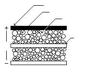
Figure 1 Block diagram of supercapacitor
As can be seen from the figure, the porous electrode is made of porous activated carbon which has a large surface area to adsorb charges in the electrolyte, and thus will have a large capacitance and can store a large amount of electrostatic energy, which is a supercapacitor. One characteristic is between the traditional capacitor and the battery. Between the batteries, although the energy density is 5% or less, the energy storage method can also be applied to the conventional battery shortage and short-term high peak current. This supercapacitor has several features that are better than batteries. 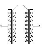
Figure 2 Supercapacitor block diagram
1. The electric capacity is large, and the area of ​​the supercapacitor using activated carbon powder and activated carbon fiber as the polarizable electrode in contact with the electrolyte is greatly increased. According to the calculation formula of the electric capacity, the larger the surface area of ​​the two-pole plate, the larger the electric capacity. Therefore, the capacity of a typical electric double layer capacitor easily exceeds 1F, and its appearance has suddenly increased the capacity range of ordinary capacitors by three to four orders of magnitude. At present, the maximum capacity of a single supercapacitor can reach 5000F. 
Since the equivalent series resistance (ESR) is larger than that of a normal capacitor, the voltage drop generated by ESR during charging and discharging is not negligible. For example, the ESR of a 2.7V/5 000F supercapacitor is: 0.4mΩ, and the ESR voltage drop at 100A current discharge is 40mV accounts for 1.5% of the rated voltage. The ESR voltage drop at 950A current discharge is 380mV, which accounts for 14% of the rated voltage, indicating that the discharge capacity will be 88.5% of the rated capacity at rated current. This characteristic will be shown in Figure 3. see. 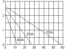
2.3 Rated current: 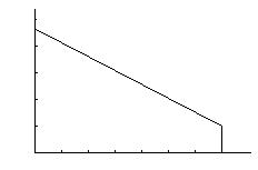
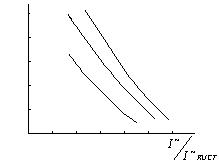
2.13 fever: