Recently, my students have frequently experienced the phenomenon of “crackingâ€: the seemingly simple design, but it can’t be adjusted, and people are going crazy. About a week ago, when Xiao Chen came to me, he couldn’t grasp the branches on the cliff. He wanted to let himself jump off the cliff. The monkeys wanted to tell me something obsessive. In these two days, Xiao Chen’s problem was solved, solved, and happy again. But Chang Wei’s problem is coming again. The MSP430F169 MCU is used to implement SPI control for the program-controlled gain amplifier PGA280. Normally, the same MCU can control a 24-bit ADS1259, which is also normal. But both are soldered at the same time, and it is not possible to control them separately with CS chips. The problem is as simple as that, but it makes him feel bad. Solving the problem is a matter of time. I don't worry, and I find that the problem is solved. It is exercise for them. I am happy. However, I found that they were in a state of chaos without exception: there was a problem, start to try left, try right, sometimes succeed, happy, eat back, no longer, and then try. Just so repeatedly toss, when there is always a breakdown, they start to get angry, anxious, and then the world to find someone to help, especially after falling into the water to find straw. This state lasted for more than 3 days and they started to get angry with me. I told them that the failure is a good thing, the first exercise for you, the second rule out the hidden dangers. When it is not a last resort, I will not be able to go out. I only need to teach them the three major requirements for troubleshooting. Troubleshooting is a matter of learning, and it is very good. But the cage and the system, the three must, with these three, there is no troubleshooting can not be checked: first, mentality. Second, strategy. Third, patience. The first state of mind. You must be strongly grateful for the failure that has occurred. Thank you, God gave me this opportunity, I have to hold it firmly. You can imagine that you are Holmes. You haven't been working for a few months. It's no longer interesting to chat with Watson every day. I am eager to have a case. The Scotland Yard is helpless and waiting for you to go out. Only this kind of mentality can enable you to maintain an energetic mind, meticulous thinking and patience in the long-term struggle. My biggest feature is here. When students report faults to me, I am usually very excited, listening to words, like listening to questions, they are careless, my eyes are sharp. I especially hope that my students can learn this. The second strategy. This is technical work. Speak too much, and talk a little. 1) Repeat the fault to avoid random failure. For random failures, I am looking for another opportunity. 2) Protect the fault scene and not easily move. Whether it is software or hardware, it should be guaranteed to recover. Therefore, don't solder the chip at will, the chip under soldering should be placed and can be retrieved. In addition, the software must be backed up by serial number. 3) Don't make more than two changes at a time. 4) Develop habits and record all actions and facts with a small book. Changed a power supply, it seems like a trivial matter, it may be changed from A fault to B fault, your mind will be chaotic. Therefore, if you want to change the power supply, also record. 5) Emphasis on instruments and methods of operation. Every time you record facts, make sure the facts are true. 6) Learn to use logical thinking. Mainly, there are many possibilities for causing such a phenomenon of failure, one by one, the most likely to be the least likely. 7) Learn the order of investigation. There are two main factors affecting the troubleshooting sequence, the first failure probability, and the second troubleshooting difficulty. Of course, we must first test the most likely and the least difficult to check. But the two are not always so smart. For example, if you suspect that the A chip is broken, this is the most likely. However, it is very difficult to weld it, and it is difficult to carry out the inspection. You can check other possibilities first. This is a bit of luck and a bit of experience. 8) Learn the dichotomy and use it skillfully. The dichotomy is to divide the fault into two parts (or three parts, not too much, otherwise it will be chaotic), and then create some situations, find a way to determine which part, then subdivide, and gradually narrow the encirclement. In the past, when the Japanese devils checked the city, they used this method: a region and a regional power outage, to see where a power outage caused the telegraph signal to disappear, you can determine which area the sender is in, then narrow the regional power outage, and finally find Our underground workers. A few words are still unclear, I will look for opportunities to talk about it. You should be more excited when you list all the possibilities of failure according to this meticulous way of thinking, and when there is no result in all investigations. Just like adding a 1V DC voltage to a 1k resistor, the measured current is not 1mA. You should have this mentality: It’s a ghost, isn’t Ohm’s law true? At this point, find a teacher, find a friend, find someone to do. But who is doing this? Most students are at this stage and have completely collapsed.
Rigid PCB is a kind of Printed Circuit Board, and is the largest number of PCB manufactured. It is made of solid substrate material, which can effectively prevent the distortion of the circuit board. Perhaps the most common rigid PCB is the computer motherboard. The motherboard is a multi-layer PCB designed to distribute power from the power supply while allowing communication between all components of the computer, such as CPU, GPU and RAM.
Multilayer Rigid PCB Stackup
Learn more about JHY PCB by exploring the manufacturing capability of Rigid Printed Circuit Board below. We can do more than you can imagine.
Item
Manufacturing Capability
PCB Layers
1-26L (TG135 TG150 TG170 TG180)
Laminate
FR-4, FR- 406, 370 HR ,IT180A,CEM-1, CEM-3,FR1,FR2,94HB,PTFE,etc.
Brand of Laminate
Kingboard,Shengyi,Nanya,Isola,Rogers,etc.
Max Board Size
1-2layers: 1000mm * 600mm
Multilayer PCB: 600* 600mm
Board Thickness
0.1-4.0 mm
Board Thickness Tolerance
±10%
Copper Thickness
1-10 oz
Min Mechanical Drilling Hole Size
4mil(0.10mm)
Min Laser Drilling Hole Size
3mil(0.075mm
Min Line Width/Line Space
2/2mil
Surface Finishes
OSP, HASL, HASL Lead-Free (HASL LF), Immersion Gold(ENIG), Immersion Silver, Immersion Tin, Plated Gold, etc.
Solder Mask Colors
Green, Red, White, Black, Blue, Yellow, Orange, Purple, Gray.
Silkscreen Colors
Black, White, Yellow.
Electrical Testing
Fixture and Flying Probe
Other Testing
AOI, X-Ray(AU&NI), Two-dimension Measurement, Hole Copper Instrument, Impedance Test, Metalloscope, Peeling Strength Tester, Solderability Test, Logic Contamination Test
Special Capabilities
Thick Copper, Thick Gold(60μ"), Gold Finger, Blind and Buried Hole, Countersink Hole, Semi-hole, Peelable Mask, Carbon Ink, Impedance control+/- 10%, etc.
Additional information Rigid PCB Rigid PCB,Fr4 PCB,Rigid Circuit Board,Rigid Printed Circuit Board JingHongYi PCB (HK) Co., Limited , https://www.pcbjhy.com
Rigid PCB , the largest number of PCB manufactured
What is Rigid PCB - Rigid PCB Definition
Rigid PCB can be used in any position where the PCB itself needs to be set to a shape and maintained during the remaining life of the equipment. Rigid PCBs can be anything from simple single-layer PCBs to eight or ten-layer multi-layer PCBs.
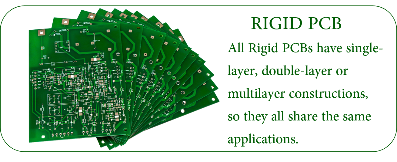
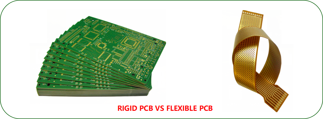
Rigid PCB and Flexible PCB are totally different. One is flexible and the other is rigid. Therefore, their application scenarios are different. In addition, there are Rigid Flex PCB . There are similarities between them. However, all rigid PCB have single-layer, double-layer or multi-layer structure, so they have common application scope. This is the case.

Some characteristics of rigid PCB
Rigid PCB Manufacturing
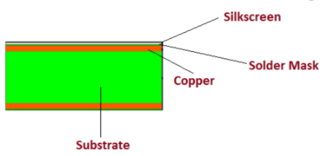
Rigid PCB is made up of different layers that are joined together using adhesive and heat, providing a solid shape to board material. Following layers are used to develop a rigid PCB.
Substrate Layer - rigid PCB material


Copper Layer
Solder Mask Layer
Silkscreen Layer

The differences between Rigid PCB And Flexible PCB
When to Use Rigid and When to Use Flexible
Rigid PCB Applications
Rigid Printed Circuit Board Manufacturer: Guaranteed Quick Delivery
JHY PCB is committed to providing the highest quality rigid Printed Circuit Boards at competitive prices. As the name suggests, these PCBs use an inflexible, solid, and rigid substrate material such as fiberglass, which prohibits these boards from bending. We can provide high-quality, and performance-oriented rigid printed circuit boards in diverse specifications.
Different Types of Rigid PCB Provided by JHY PCB
Matt: Green, Blue, Black.