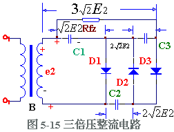
Triple voltage rectifier circuit diagram: In the actual circuit, the voltage on the load is Usc = 2X1.2E2. The highest reverse voltage experienced by rectifier diodes D1 and D2 On the basis of the double voltage rectification circuit, a rectifier diode D3 and a filter capacitor C3 are added to form a triple voltage rectifier circuit, as shown in Figure 5-15. The working principle of the triple voltage rectifier circuit is: in the first half cycle and the second half cycle of e2 , the same as the double voltage rectifier circuit, that is, the voltage on C1 is charged. In the actual circuit, the voltage on the load Ufz ≈ 3x1.2E2 rectifier diode D3 is also the highest reverse voltage In this way, by adding multiple diodes and the same number of capacitors, it is possible to form a multiple voltage rectifier circuit, see Figure 5-16. When n is an odd number, the output voltage is taken from the upper end: when n is an even number, the output voltage is taken out from the lower end. It must be stated that the voltage doubler rectifier circuit can only work when the load is light (ie, Rfz is large and the output current is small), otherwise the output voltage will decrease. The higher the voltage doubler, the more obvious the increase in output voltage due to the increase in load current.
Easy Electronic Technology is the leading supplier of 6gpu 8gpu 12gpu chassis supplier and factory
Best Efficient Mining Rig with Stronger Frame, Quiet Working,
1x Windows 10 mining rig system installation
Applicable mining: mining rigs for sale,best miner for ethereum,gpu mining rig for sale,ethereum mining rig for sale Easy Electronic Technology Co.,Ltd , https://www.pcelectronicgroup.com![]() . DC voltage Uc1 on the capacitor
. DC voltage Uc1 on the capacitor ![]() , Uc2=
, Uc2= ![]() . Circuits and selection components can be designed accordingly.
. Circuits and selection components can be designed accordingly. ![]() , the voltage on C2 is charged close to
, the voltage on C2 is charged close to ![]() . When the third half is over, D1 and D3 are turned on, D2 is turned off, the current is charged by C1 except D1, and C3 is charged by D3. The charging voltage Uc3 on C3 = e2 peak + Uc2 - Uc1≈
. When the third half is over, D1 and D3 are turned on, D2 is turned off, the current is charged by C1 except D1, and C3 is charged by D3. The charging voltage Uc3 on C3 = e2 peak + Uc2 - Uc1≈ ![]() Thus, on RFZ,, the DC voltage Usc=Uc1i+Uc3 can be output.
Thus, on RFZ,, the DC voltage Usc=Uc1i+Uc3 can be output. ![]() +
+ ![]() =3√2 E. , to achieve triple voltage rectification.
=3√2 E. , to achieve triple voltage rectification. 
![]() The DC voltage on the capacitor is
The DC voltage on the capacitor is ![]() .
.
Package includes
1x 8 GPU Mining chassis rig machine
1x 8 Port Motherboard
1x Intel CPU
1x 64GB mSATA SSD
1x 4GB DDR3L SODIMM RAM Module (upgradeable to 16GB)
4x 120MM High Flow Fans
1x 1800W Power Supply(1800W\2000W\2500W Optional)
1x ATX Power Cable
ETH/ETC/AE/BTM/GRIN/GRIN31/BEAM/SERO/RVN/MONA/CKB/XVG/BCD/FIRO/HYC/VTC/CLO/RVC/PGN/CHI etc.