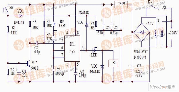
Typical anti-interference timer circuit The figure is a typical anti-interference timer circuit diagram. The principle of the circuit: When the SB is disconnected, the 4 pin of the 555 is connected to the ground through the resistor R6, and the 555 circuit is forcibly reset. At this time, the 555 circuit does not work regardless of how much interference is caused by the 2 feet. When button B is pressed, the power supply is applied to the 4-pin high level through the diode VD1, the forced reset function of the time base circuit is released, and the power supply is applied to the base of the transistor VT1 through the resistor R1, so that VT1 is turned on, and the capacitor is turned on. C2 is connected to the VT1 collector and outputs a low level to the 2 pin of the IC circuit, the IC is turned over, the 3 pin outputs a high level, the LED is lit, the relay K is energized, the contact K-1 is closed, and the socket is closed. External power supply, while the high level of 3 feet through VD2 output a high level to 4 feet makes the circuit self-locking. When the transient ends, the circuit returns to steady state, the 3 pin outputs low level, the relay K loses power, the contact K-1 is disconnected, and the circuit returns to the initial state. HD Mini Projector-1080P high-resolution display, magnify the details and present a clear picture, without any distortion in direct projection. The LED light source system integrates color control to improve the brightness, quality and stability of the picture, and present the real world in front of your eyes. led home projector 1080p,1080p home cinema projector,wifi 1080p home theater projector Shenzhen Happybate Trading Co.,LTD , https://www.happybateprojectors.com