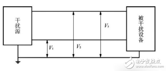
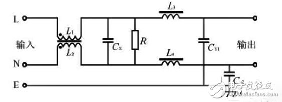
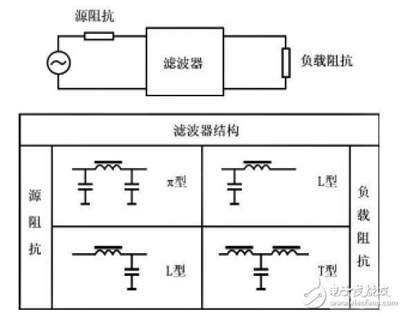
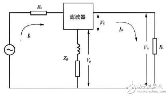
With the rapid development of modern science and technology, electronic, power electronics, and electrical equipment are becoming more and more widely used. The high-density, wide-spectrum electromagnetic signals generated by them in operation fill the entire space and form a complex electromagnetic environment. Complex electromagnetic environments require electronic equipment and power supplies with higher electromagnetic compatibility. Therefore, the technology for suppressing electromagnetic interference has also received more and more attention. Grounding, shielding and filtering are the three major measures to suppress electromagnetic interference. The following mainly introduces the EMI filter used in the power supply and its basic principle and correct application method. The power supply of electronic equipment, such as 220V/50Hz AC grid or 115V/400Hz alternator, has various EMI noises, including artificial EMI interference sources, such as radio transmission of various radar, navigation, communication and other equipment. The signal will induce electromagnetic interference signals on the power cable and the connecting cable of the electronic device. The electric rotating machine and the ignition system will generate transient process and radiated noise interference in the inductive load circuit. There are also natural interference sources such as lightning. The phenomenon of discharge and the interference of noise in the universe, the former has a short duration but a large energy, and the latter has a wide frequency range. In addition, thermal noise is generated when the electronic circuit components themselves operate. These electromagnetic interference noises, through the coupling of radiation and conduction, can affect the normal operation of various electronic devices operating in this environment. On the other hand, electronic devices also generate a variety of electromagnetic interference noise during operation. For example, digital circuits use pulse signals (square waves) to represent logical relationships. Fourier analysis of their pulse waveforms shows that the harmonic spectrum is very wide. In addition, there are a variety of pulse trains with repeated frequencies in the digital circuit. These pulse trains contain more harmonics, wider spectrum, and more complicated electromagnetic interference noise. Various types of regulated power supplies are themselves a source of electromagnetic interference. In a linear regulated power supply, the unidirectional pulsating current formed by rectification also causes electromagnetic interference; the switching power supply has the advantages of small size and high efficiency, and is widely used in modern electronic equipment, but because it is in power conversion When it is in the state of switching, it is a very strong source of EMI noise, and its EMI noise has a wide frequency range and high intensity. These electromagnetic interference noises also pollute the electromagnetic environment by radiation and conduction, thus affecting the normal operation of other electronic devices. For electronic equipment, when EMI noise affects the analog circuit, the signal-to-noise ratio of the signal transmission is deteriorated. In severe cases, the signal to be transmitted is overwhelmed by EMI noise and cannot be processed. When EMI noise affects digital circuits, it can cause logic errors and lead to erroneous results. For the power supply device, in addition to the power conversion circuit, there are also a drive circuit, a control circuit, a protection circuit, an input/output level detection circuit, etc., and the circuit is quite complicated. These circuits are mainly composed of general-purpose or application-specific integrated circuits. When a malfunction occurs due to electromagnetic interference, the power supply is stopped, and the electronic device cannot work normally. The use of the grid noise filter can effectively prevent the power supply from malfunctioning due to external electromagnetic noise interference. In addition, part of the EMI noise entering from the power input terminal may appear at the output end of the power supply. It generates an induced voltage in the load circuit of the power supply, which causes the circuit to malfunction or interfere with the signal transmitted in the circuit. These problems can also be prevented by noise filters. The effect of using a noise filter in a power supply device is as follows: (1) Preventing external electromagnetic noise from interfering with the operation of the control circuit of the power supply device itself; (2) Preventing external electromagnetic noise from interfering with the load of the power supply; (3) suppressing EMI generated by the power supply device itself; (4) Suppressing EMI generated by other devices and transmitted through the power supply. When the switching power supply itself is working and the electronic equipment is in the working state of the switch, terminal noise will appear at the input end of the power supply device, generating radiation and conduction interference, and also entering the AC power grid to interfere with other electronic devices, so effective measures must be taken to suppress . Electromagnetic shielding is the best way to suppress radiated interference from EMI noise. In terms of suppressing conducted interference of EMI noise, the use of EMI filters is a very effective means, and of course, good grounding measures should be used. In the world, strict electromagnetic noise restriction rules have been implemented in various countries, such as FCC in the United States and FTZ and VDE in Germany. If the electronic device does not meet the noise limit rules, the product cannot be sold and used. For all of the above reasons, it is necessary to design and use a grid noise filter that meets the requirements in the power supply equipment. There are two types of EMI noise on the input leads of the power supply: common mode noise and differential mode noise, as shown in Figure 1. The EMI noise existing between the AC input lead and the ground is called its common mode noise, and it can be regarded as an interference signal having the same potential and the same phase transmitted on the AC input line, that is, the voltages V1 and V2 of FIG. The EMI noise existing between the AC input leads is called differential mode noise, and it can be regarded as an interference signal with a phase difference of 180° transmitted on the AC input line, that is, the voltage V3 in FIG. The common mode noise is the interference current flowing from the AC input line to the earth, and the differential mode noise is the interference current flowing between the AC input lines. Conducted EMI noise on any power supply input line can be represented by common mode and differential mode noise, and these two types of EMI noise can be considered as independent EMI sources to suppress. When suppressing electromagnetic interference noise, it is mainly considered to suppress common mode noise, because common mode noise accounts for the main part in the full frequency domain, especially in the high frequency domain, and the differential mode noise accounts for a large proportion in the low frequency domain, so it should be based on This feature of EMI noise is used to select the appropriate EMI filter. The noise filter for power supply can be divided into an integrated type and a discrete type according to the shape. The integrated type encapsulates an inductor coil, a capacitor, etc. in a metal or plastic case; the discrete type mounts an inductor coil, a capacitor, etc. on a printed board, and constitutes a noise suppression filter. Which form to use depends on cost, characteristics, installation space, etc. The integrated cost is high, the characteristics are good, the installation is flexible; the discrete cost is low, but the shielding is not good, and it can be freely distributed on the printed board. The power EMI noise filter is a passive low-pass filter that transmits AC power to the power supply without attenuation, and greatly attenuates the EMI noise transmitted with the AC power. At the same time, it can effectively suppress the EMI noise generated by the power supply device and prevent it. They enter the AC grid and interfere with other electronic devices. The basic structure of the single-phase AC grid noise filter is shown in Figure 2. It is a four-terminal passive network composed of lumped parameter components. The main components used are common mode inductors L1 and L2, differential mode inductors L3 and L4, and common mode capacitors CY1 and CY2 and differential mode capacitor CX. If this filter network is placed at the input of the power supply, L1 and CY1 and L2 and CY2 respectively form a low-pass filter between the two independent ports on the AC incoming line, which can attenuate the common mode interference existing on the AC incoming line. Noise, preventing them from entering the power supply. The common mode inductor is used to attenuate the common mode noise on the AC incoming line. L1 and L2 are generally wound in the same direction on the ferrite core of the closed magnetic circuit, and are connected to the circuit in L1 and L2. The magnetic fluxes generated by the alternating currents in the coils cancel each other out, so that the magnetic core does not cause saturation of the magnetic flux, and the inductance values ​​of the two coils are larger in the common mode state and remain unchanged. The differential mode inductors L3 and L4 and the differential mode capacitor CX form a low-pass filter between the AC inlet independent ports to suppress differential mode interference noise on the AC inlet line and prevent the power supply device from being disturbed by it. The power supply noise filter shown in Figure 2 is a passive network with bidirectional suppression. Insert it between the AC grid and the power supply, which is equivalent to adding a blocking barrier between the EMI noise of the two, so that a simple passive filter acts as a two-way noise suppression, thus enabling various electronic devices. It has been widely used. The magnetic core used in the common mode inductor has a ring shape, an E shape and a U shape. The material is generally ferrite. The toroidal core is suitable for large current and small inductance. Its magnetic path is longer than E and U shapes, and there is no gap. A larger amount of inductance can be obtained with fewer turns, and it has better frequency characteristics due to these characteristics. However, the leakage flux of the E-shaped magnetic core is small, so when the leakage current of the inductor may affect the magnetic coupling between other circuits or other circuits and the common mode inductance, and the required noise attenuation effect cannot be obtained, the E-shaped magnetic core should be considered. Common mode inductance. The differential mode inductor coil generally adopts a metal powder magnetic core. Since the powder magnetic core has a low frequency range, the DC superposition characteristic is good in several tens of kHz to several MHz, and the inductance does not greatly decrease in a large current application. Most suitable as a differential mode inductor. In Figure 2, the power supply noise filter uses two types of capacitors, CX, CY1, and CY2, which have different roles in the filter and different safety level requirements, so their performance parameters are directly related to the safety performance of the filter. The differential mode capacitor CX is connected to the two ends of the AC incoming line. In addition to the rated AC voltage, it also superimposes various EMI peak voltages existing between the AC incoming lines. Therefore, the performance requirements of the capacitor's withstand voltage and transient peak voltage resistance are high, and the capacitor is required to fail, which cannot endanger the rear circuit and personal safety. The safety level of CX capacitors is divided into two categories: X1 and X2. X1 is suitable for general applications, and X2 is suitable for applications where high noise peak voltage will occur. The common mode capacitor CY is connected between the AC input line and the chassis ground, and they are required to have sufficient safety margin in terms of electrical and mechanical performance. In case they are short-circuited, the equipment casing will be dangerous. AC power, such as the insulation or grounding protection of the equipment, may cause electric shock to the operator and even endanger personal safety. Therefore, the capacity of the CY capacitor should be limited so that the leakage current at the rated frequency is less than the safety specification. It is also required to have sufficient voltage withstand and transient high peak voltage margin, and in case of voltage breakdown it should be in an open state without charging the equipment case. In summary, when designing and selecting grid noise filters, because they operate in high voltage, high current, and harsh electromagnetic interference environments, the safety performance of the inductors and capacitors used must first be considered. For the inductor coil, the core, the material of the winding, the insulation material and the insulation distance, and the temperature rise of the coil should be taken seriously. For capacitors, the type of capacitor, withstand voltage, safety level, capacity, leakage current, etc. should be given priority, especially for products that have been certified by international safety agencies. 6.1 Filter and leakage current The grid filter leakage current is defined as the current from the filter housing to either end of the AC incoming line at rated AC voltage. If all ports of the filter are completely insulated from the case, the value of the leakage current depends mainly on the leakage current of the common mode capacitor CY, that is, mainly depending on the capacity of the CY. Due to the leakage current of the filter, it involves personal safety. International countries have strict standards for this. For 220V/50Hz AC grid power supply, the leakage current of the noise filter is generally required to be less than 1mA. 6.2 Filter and test voltage For the AC grid noise filter, the test voltage is divided into two types: one is applied to the two ends of the AC inlet line, that is, the line-to-line test voltage. If the inductor coil and the lead wire are well insulated, it mainly depends on the withstand voltage of the capacitor CX; the other is applied between either end of the AC incoming line and the chassis ground, that is, the line-ground test voltage. It mainly depends on the withstand voltage of CY. Leakage current and test voltage are the safety performance parameters of the noise filter. They are the specific performance of the safety performance of the inductor, insulation and capacitor CX and CY in the filter, and are closely related to equipment and personal safety. Therefore, in the design, production and use of grid noise filters, special attention should be paid to the certification and inspection of these technical parameters. (1) Insertion loss is one of the important technical parameters of the noise filter, and should be considered mainly in the design and selection. When the filter safety, conventional electrical performance, environmental and mechanical conditions are all met, the insertion loss value should be chosen as large as possible. The definition of insertion loss is shown in Figure 3. When the filter is not connected, the output voltage of the signal source is V1. When the filter is connected, the voltage of the signal source is measured at the output of the filter as V2. If the output impedance of the signal source is equal to the input impedance of the receiver, both are 50Ω, then the insertion loss of the filter is: IL=20log(V1/V2)(1) Because the power supply noise filter attenuates common mode and differential mode noise, it has common mode insertion loss and differential mode insertion loss. However, when actually selecting the filter, it should be noted that the insertion loss curve given in the product manual is measured according to the standard, and its input and output impedances are both 50Ω. Since the actual impedance across the filter is not necessarily 50Ω over the full frequency range, its attenuation of the EMI signal is not equal to the insertion loss value given in the product manual. Especially when the installation is not properly installed, it will be much smaller than the standard given insertion loss. (2) The power supply noise filter is a passive network with reciprocity. In practical applications, it should be reasonably matched in order to effectively suppress noise. According to the combination shown in Figure 4, the network structure and parameters of the filter are selected to obtain better EMI suppression. When the output impedance of the filter is not equal to the load impedance, a reflection will occur on this port. The greater the difference between the two impedances, the greater the reflection from the port. When the impedance across the filter is not equal to the external impedance, the EMI signal will reflect at both its input and output. At this time, the attenuation of the electromagnetic interference noise by the power supply filter is related to the insertion loss and the reflection loss inherent to the filter, and this point can be utilized to more effectively suppress the electromagnetic interference noise. When actually designing and selecting an EMI filter, pay attention to the correct connection of the filter impedance to cause as much reflection as possible, so that the filter causes a large impedance mismatch over a wide frequency range, resulting in better Electromagnetic interference suppression performance. (3) In the practical application of the power supply filter, it is required to have a good electrical connection between the outer casing and the system ground, and the grounding wire should be as short as possible, because the excessively long grounding wire will increase the grounding resistance and inductance, and serious Reducing the common-mode rejection of the filter also creates the problem of common ground-impedance coupling. As shown in Figure 5, if the ground line is too long, the common coupling impedance Zg between the input and output of the filter is too large. The voltage on the load is: V0=VZ+Vg=VZ+(Ii-IO)Zg(2) where: Ii is the noise current of the filter AC input circuit; IO is the noise current of the filter output circuit. It can be known from equation (2) that after the electromagnetic interference signal is attenuated by the filter, the noise current at the output end is much smaller than the noise current at the input end, that is, the voltage drop (Ii-IO) Zg caused by the common ground impedance will be large, and will be on Zg. A very high electromagnetic interference voltage is generated, coupled to the output of the filter through a common ground loop, thereby greatly reducing the noise filter's ability to suppress EMI noise. The best way to reduce the common impedance coupling is to isolate the input end of the noise filter from the output by means of the electromagnetic shielding of the device, and the ground line of the filter should be as short as possible so that the filter input and output are both The existing electromagnetic coupling is minimized without damaging the shielding effect of the shielding structure of the device on electromagnetic interference noise. The ideal power supply noise filter installation is shown in Figure 6. (4) In summary, the use of power supply noise filters should pay attention to the following points: 1 The filter should be installed as close as possible to the AC inlet of the equipment, so that the AC inlet without the filter should be as short as possible in the equipment; 2 The capacitor leads in the filter should be as short as possible to prevent the lead inductance and capacitive reactance from resonating at lower frequencies; 3 A large current flows through the filter ground line, which generates electromagnetic radiation and should be well shielded and grounded. 4 The input and output lines of the filter cannot be bundled together. When wiring, try to increase the distance between them to reduce the coupling between them. A spacer or shielding layer can be added. The design and selection of electromagnetic interference filters are mainly based on the noise interference characteristics and the requirements of system electromagnetic compatibility, based on understanding the frequency range of electromagnetic interference and estimating the approximate magnitude of interference. First of all, we must understand the environment in which the filter is used (voltage, load current, ambient temperature and humidity, vibration shock, installation method and position). It is important to consider its safety performance parameters because it is related to equipment and personal safety. Also make the filter have the best suppression of EMI noise. The network structure and parameters of the filter should be selected based on the requirements of the access circuit to produce the maximum impedance mismatch. In order to obtain the best electromagnetic noise attenuation characteristics, the filter should be properly mounted on the electronic device.
RJ45 connectors mostly used for data communication . SVLEC provide Male Female straight angle .RJ45 shielded connector with 4-pole 8-pole , Protection degree IP20 with Quick connection technology .Plastic or metal housings with good resistance against chemicals and oils. The resistance to aggressive media should be individually tested for your application. Further details on request.
Rj45 Connector,Rj45 Cat5 Connector,8Pin Rj45 Connector,RJ45 Shielded Connector, RJ45 connector 4 pin Kunshan SVL Electric Co.,Ltd , https://www.svlelectric.com


![}A(]M{5CKN@L01W(WDP`]PS }A(]M{5CKN@L01W(WDP`]PS](http://i.bosscdn.com/product/80/bf/88/c48b0c48b2c9627adb4dc02ce1.png)
Analysis of the design and selection of the EMI filter (for you to answer the filter device of the circuit!)
1 Introduction