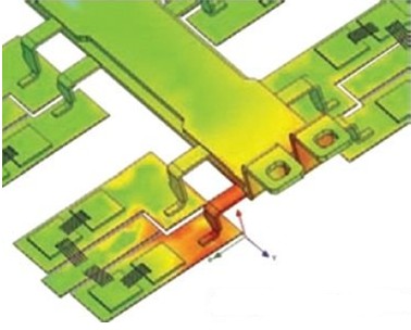
In the highly competitive hybrid and electric vehicle (HEV/EV) market, power integration R&D engineers are challenging higher system efficiency, stability and reliability. This article refers to the address: http:// Power inverters are critical in power integrated systems and typically consist of six IGBT modules in a 4 x 6 inch package. These IGBT modules control the output of AC to the motor by switching hundreds of amps of current quickly, controlling electronic systems and other systems. The switching frequency of the IGBT ranges from tens of kHz to hundreds of kHz, and the turn-on rise time and turn-off fall time are 50 to 100 ns. The high switching speed makes the IGBT very suitable for power inverter systems but it also brings two major electromagnetic problems: conducted radiation (via current-carrying structures) is usually below 30MHz, which can cause power supply integrity problems or cause inverse There are potentially harmful energy reflections in transformers and motors; radiated electromagnetic fields (through air) are typically above 30 MHz and may affect other electronic systems in the vehicle. In order to comply with government and international vehicle electromagnetic radiation standards, the above two types of interference problems must be fully considered in the design. Therefore, the responsible engineer must design the electromagnetic compatibility and electromagnetic interference of the basic structural components of the system. To complete the electromagnetic compatibility and electromagnetic interference design of a power inverter system, engineers must first address the potential physical factors that determine electromagnetic compatibility and electromagnetic interference, and then complete the design with the help of circuits and systems. This simulation-driven approach facilitates handling of other electromagnetic issues that must be considered, including current quality, power consumption, and overall system efficiency. These calculations are often performed using linear circuit components and simplified circuit solvers that require a large number of rough approximations and oversimplification assumptions. By skipping the simulation of these vital fundamental physics mechanisms, the simulation results will no longer be correct, and hardware prototype testing may be required before the performance requirements are met - multiple iterations of redesign. In most cases, these test cycles are not carried out until the later stages of the design process, so the cost will increase significantly and market opportunities will be missed. Simulations without multiple physical domain problems are impossible to predict the effects of electromagnetics before power inverter manufacturing and early in development. The Ansoft software package provides a full frequency domain multiphysics problem analysis tool for electromagnetic performance studies of devices such as IGBTs. Ansoft's expertise is in electromagnetic field simulation, as well as simulation of circuits and systems. Ansoft tools that can be used for power inverter development include: HFSS: A finite element based full wave solver that can be used to extract parasitic parameters and display 3D electromagnetic fields. Simplorer: A multi-domain circuit and system simulator that easily integrates multiple physical domain simulation components such as electrical, thermal, mechanical, magnetic, and fluid. Q3D Extractor: A quasi-static electromagnetic field solver that can be used to calculate conductance parameters in frequency-dependent resistors, inductors, capacitors, and current-carrying structures. In order to accurately describe the performance of switching devices such as IGBTs, engineers typically start with a parametric wizard that can be used to import IGBT performance curves and tabular data from a vendor-supplied performance sheet. The data processing program automatically extracts the required parameters (approximately 140) to generate the semiconductor circuit model of the IGBT without manual completion. The design layout of the power converter can then be imported directly into the Q3D Extractor tool from the CAD software or layout design tool. Q3D Extractor calculates the frequency-dependent resistance, part of the inductance and capacitance of the conductive path from the design layout. Engineers use the tool to generate an equivalent circuit model for system simulation in Simplorer. Once the model is built, it can be combined with a semiconductor circuit model to form the electrical integrity model of the IGBT. Electrical integrity models can be used for conducted radiation analysis of power supplies, control systems, and loads. The results of this simulation can be used by HFSS to verify radiated emissions - a type of radiation that is of particular interest in view of the frequency domain harmonics caused by fast on-off time series. To determine this effect, Simplorer's results can be used as input to the HFSS full-wave electromagnetic solver. Engineers can then fully understand their radiated electromagnetic fields and calculate the electromagnetic field strength at any given point in the space and determine if the inverter package meets relevant standards. In this way, engineers can use the tools provided by Ansoft to design the electromagnetic compatibility and electromagnetic interference of the inverter system, and trace the electromagnetic performance to the layout of the inverter. Thus, parameter changes are made to the design and a series of simulation results are obtained until the conducted and radiated electromagnetic emission levels are within acceptable limits. The value of this approach is that once the model is completed, the design can be modified by changing several key parameters, allowing engineers to study a variety of different parameter schemes and make hypothetical analysis explorations over a wide range. This approach provides a design result that satisfies performance requirements and is fully optimized before manufacturing without hardware. Compared to the prototype-prototype test mode, the multi-physics simulation method saves time and money, and enables the company to participate in market competition with better designed products.
ZGAR AZ MC Disposable
ZGAR electronic cigarette uses high-tech R&D, food grade disposable pod device and high-quality raw material. All package designs are Original IP. Our designer team is from Hong Kong. We have very high requirements for product quality, flavors taste and packaging design. The E-liquid is imported, materials are food grade, and assembly plant is medical-grade dust-free workshops.
Our products include disposable e-cigarettes, rechargeable e-cigarettes, rechargreable disposable vape pen, and various of flavors of cigarette cartridges. From 600puffs to 5000puffs, ZGAR bar Disposable offer high-tech R&D, E-cigarette improves battery capacity, We offer various of flavors and support customization. And printing designs can be customized. We have our own professional team and competitive quotations for any OEM or ODM works.
We supply OEM rechargeable disposable vape pen,OEM disposable electronic cigarette,ODM disposable vape pen,ODM disposable electronic cigarette,OEM/ODM vape pen e-cigarette,OEM/ODM atomizer device.
ZGAR AZ MC Vape,ZGAR AZ MC Vape disposable electronic cigarette,ZGAR AZ MC vape pen atomizer ,AZ MC E-cig,AZ CC Vape disposable e-cigarette Zgar International (M) SDN BHD , https://www.szdisposable-vape.com


