Household Appliances Zinc Alloy Die Casting Household Appliances Zinc Alloy Die Casting,Surface Finish Zinc Casting,Handle Door Lock Parts,Zinc And Aluminum Casting Dongguan Metalwork Technology Co., LTD. , https://www.dgdiecastpro.com
The MAX6954 / MAX6955 are 4-wire or 2-wire serial interface LED drivers that can control 7, 14, or 16-segment LEDs or a 16x8 LED matrix. The driver also includes 5 I / O expansion (GPIO) ports, and all logic controls that use these ports to automatically scan 32 buttons to eliminate button jitter. Another function option is to notify the system processor to eliminate key jitter through an interrupt pin. The extended key scan scheme introduced in this article (from 32 keys to 80 or more keys) requires additional diodes.
Table 1. Standard 32-key connection for MAX6954 / MAX6955 P0 P1 P2 P3 LED Output O0 SW A1 SW B1 SW C1 SW D1 LED Output O1 SW A2 SW B2 SW C2 SW D2 LED Output O2 SW A3 SW B3 SW C3 SW D3 LED Output O3 SW A4 SW B4 SW C4 SW D4 LED Output O4 SW A5 SW B5 SW C5 SW D5 LED Output O5 SW A6 SW B6 SW C6 SW D6 LED Output O6 SW A7 SW B7 SW C7 SW D7 LED Output O7 SW A8 SW B8 SW C8 SW D8 
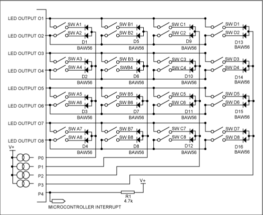
Figure 1. Standard 32-key connection of MAX6954 / MAX6955
Table 1 and Figure 1 show the standard 8-key connection of the MAX6954 / MAX6955. The key switching circuit reads the state of 32 keys in a 4 x 8 matrix (4 columns, 8 rows). The eight rows of the keyboard array are driven by eight LED cathode driver outputs (LED output O0 to LED output O7). As part of the multi-layer LED drive, these LED cathode drive outputs are pulled to a low level of 320µs (nominal value) (sequential drive LED). These driver outputs are used to pull down one end of the key switch, and the other end of the key is connected to 4 input pins (P0 to P3). These 4 input pins are internally pulled to the high level V + of MAX6954 / MAX6955. When the switch is pressed, P0, P1, P2, or P3 will be pulled low by the corresponding LED output Ox, and the MAX6954 / MAX6955 detect the button and provide debounce for the button.
When multiple buttons are pressed at the same time, the diode in series with the switch can prevent two or more LED cathode drive output short circuit. For example, when SW A1 and SW A2 are pressed at the same time, the diode in series with the key can prevent the LED output O0 and the LED output O1 from short-circuiting, because at least one diode is reverse-biased under any circumstances. The diode uses a low-cost, common anode BAW56, SOT23 package.
The MAX6954 / MAX6955 can determine the action of pressing or releasing 32 buttons at any time. The device only provides registers for indicating the status of these 32 buttons. From this point of view, there seems to be no way to expand the scanning circuit in the design of the MAX6954 / MAX6955, and it is necessary to look for a new design scheme.
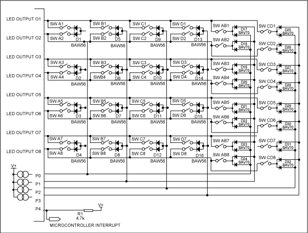
In response to this special situation, we have discovered a redundant situation. In many applications, you only need to know whether a key is pressed. Usually, the situation where two keys are pressed at the same time is considered to be an incorrect key input, or to enter the factory diagnostic mode. This kind of situation where two buttons are pressed at the same time is a "redundant" situation. We connect the newly added buttons as if a pair of buttons were pressed at the same time. , P1, P2 and P3 have expanded 16 buttons. For example, when SW AB1 is pressed, for the MAX6954 / MAX6955, the displayed state is the same as when SW A1 and SW B1 are pressed simultaneously. As long as the physical location of each pair of buttons (such as SW A1 and SW B1) is not adjacent, this extended architecture can work effectively. The software design should guarantee to respond to the / IRQ of the key within the minimum debounce period of MAX6954 / MAX6955, and ensure that each result corresponding to the key scan is properly analyzed and processed. If the software responds to / IRQ slowly, it will be impossible to distinguish between the case of pressing two buttons at the same time (identifying the added button state) and the case of pressing the same two buttons in sequence. In either case, the key debounce register 0x08-0x0B will simply display each key position bit.
Table 2. Extended 48-key connection for MAX6954 / MAX6955 P0 P1 P2 P3 P0 & P1 P2 & P3 LED Output O0 SW A1 SW B1 SW C1 SW D1 SW AB1 SW CD1 LED Output O1 SW A2 SW B2 SW C2 SW D2 SW AB2 SW CD2 LED Output O2 SW A3 SW B3 SW C3 SW D3 SW AB3 SW CD3 LED Output O3 SW A4 SW B4 SW C4 SW D4 SW AB4 SW CD4 LED Output O4 SW A5 SW B5 SW C5 SW D5 SW AB5 SW CD5 LED Output O5 SW A6 SW B6 SW C6 SW D6 SW AB6 SW CD6 LED Output O6 SW A7 SW B7 SW C7 SW D7 SW AB7 SW CD7 LED Output O7 SW A8 SW B8 SW C8 SW D8 SW AB8 SW CD8
Each additional button requires a dual diode (such as a low-cost, common-cathode BAV70, SOT-23 package). When the switch is pressed, P0 and P1 or P2 and P3 are pulled down simultaneously. 
Figure 2. Extended 48-key connection of MAX6954 / MAX6955
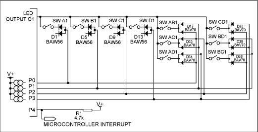
Figure 2 and Table 2 expand 16 keys by combining P0, P1, P2, and P3. In fact, there are four other possible two-key combinations for P0-P3 key scan input. If six types of two-key combinations are used, the number of keys will increase to 80, as shown in Table 3. Figure 3 shows the connection of six additional buttons on the LED output O0 line. Each additional key requires a double diode.
Table 3. MAX6954 / MAX6955 expanded 80-key connection P0 P1 P2 P3 P0 & P1 P0 & P2 P0 & P3 P1 & P2 P1 & P3 P2 & P3 LED Output O0 SW A1 SW B1 SW C1 SW D1 SW AB1 SW AC1 SW AD1 SW BC1 SW BD1 SW CD1 LED Output O1 SW A2 SW B2 SW C2 SW D2 SW AB2 SW AC2 SW AD2 SW BC2 SW BD2 SW CD2 LED Output O2 SW A3 SW B3 SW C3 SW D3 SW AB3 SW AC3 SW AD3 SW BC3 SW BD3 SW CD3 LED Output O3 SW A4 SW B4 SW C4 SW D4 SW AB4 SW AC4 SW AD4 SW BC4 SW BD4 SW CD4 LED Output O4 SW A5 SW B5 SW C5 SW D5 SW AB5 SW AC5 SW AD5 SW BC5 SW BD5 SW CD5 LED Output O5 SW A6 SW B6 SW C6 SW D6 SW AB6 SW AC6 SW AD6 SW BC6 SW BD6 SW CD6 LED Output O6 SW A7 SW B7 SW C7 SW D7 SW AB7 SW AC7 SW AD7 SW BC7 SW BD7 SW CD7 LED Output O7 SW A8 SW B8 SW C8 SW D8 SW AB8 SW AC8 SW AD8 SW BC8 SW BD8 SW CD8 
Figure 3. Extended 80-key connection of MAX6954 / MAX6955
Why only use "press two keys at the same time" as a way to judge additional keys? The 3-key and 4-key combination can be used instead of the double-key press. Table 4 shows this additional configuration. It should be noted that each group of 4-3 combination keys requires three diodes, and four groups of keys require four times the number of diodes.
Table 4. 3 key and 4 key connection P0 & P1 & P3 P0 & P1 & P4 P0 & P2 & P3 P1 & P2 & P4 P0 & P1 & P2 & P3 LED Output O0 SW ABC1 SW ABD1 SW ACD1 SW BCD1 SW ABCD1 LED Output O1 SW ABC2 SW ABD2 SW ACD2 SW BCD2 SW ABCD2 LED Output O2 SW ABC3 SW ABD3 SW ACD3 SW BCD3 SW ABCD3 LED Output O3 SW ABC4 SW ABD4 SW ACD4 SW BCD4 SW ABCD4 LED Output O4 SW ABC5 SW ABD5 SW ACD5 SW BCD5 SW ABCD5 LED Output O5 SW ABC6 SW ABD6 SW ACD6 SW BCD6 SW ABCD6 LED Output O6 SW ABC7 SW ABD7 SW ACD7 SW BCD7 SW ABCD7 LED Output O7 SW ABC8 SW ABD8 SW ACD8 SW BCD8 SW ABCD8
One of the best reasons for excluding 3 and 4 bond connections is that they require more diodes. If the required keys in the application are only slightly higher than the 32-key limit, you can first select the solution recommended in this article. It is only because of some accidental factors that it is undesirable for users to find the 3-key and 4-key solutions.
It is worth noting that the connection mode of each expansion button simulates the situation where multiple buttons are pressed at the same time. These buttons are connected to the same LED cathode driver output (LED output O0 to LED output O7). With this connection method, the keys of the related combination are always scanned or debounced at the same time. If the buttons pressed simultaneously simulated by the newly added buttons are scanned by different LED cathode driver outputs, this working method will be unreliable.
Expand the MAX6954 and MAX6955 keyboard scan to more than 32 keys
Abstract: This application note describes a method of extended scanning that can extend the keyboard scan range of the MAX6954 and MAX6955 LED display drivers, from 32 keys to 80 keys.