![]()
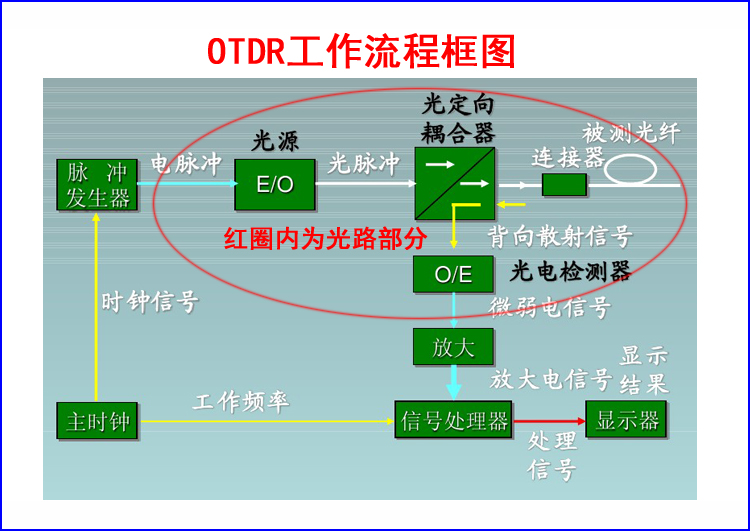
Photocoupler
Optical time domain reflectometer OTDR experience and technical common problems analysis fiber quality judgment, wavelength selection and single bidirectional test, fiber joint cleaning, fiber refractive index and scattering coefficient correction, fiber ghost (secondary reflection peak) identification and processing , fiber positive gain phenomenon processing, use of extended fiber additional fiber transition fiber
Optical time domain reflectometer OTDR experience and technical common problem analysis
(1)
Simple discrimination of fiber quality:
Under normal circumstances,
OTDR
Tested light curve body
(
Single or several optical cables
)
The slope is basically the same. If the slope of a certain section is large, it indicates that the attenuation is large. If the main body of the curve is irregular, the slope is undulating, curved or arc-shaped, indicating that the quality of the fiber is seriously degraded and does not meet the communication requirements.
(2)
Wavelength selection and single bidirectional testing:
1550
The wavelength test distance is further,
1550nm
ratio
1310nm
Fiber is more sensitive to bending,
1550nm
ratio
1310nm
Unit length attenuation is smaller,
1310nm
ratio
1550nm
The measured splice or connector loss is higher. In the actual maintenance of optical cable, both wavelengths are generally tested and compared. For both the positive gain phenomenon and the over-distance line, two-way test analysis and calculation are required to obtain a good test conclusion.
OTDR WIT780 operates at 1550nm with a dynamic range of 24dB; WIT7803 operates at 1310nm and 1550nm dual wavelengths; dynamic range is 24dB/24dB
(3)
Connector cleaning:
Fiber optic splice access
OTDR
Before, it must be carefully cleaned, including
OTDR
The output connector and the tested union, otherwise the insertion loss is too large, the measurement is unreliable, the curve is too noisy, and even the measurement cannot be performed, it may also be damaged.
OTDR
. Avoid cleaning agents or index matching fluids other than alcohol because they can dissolve the binder in the fiber optic connector. And when testing the pigtail, it should be vertically inserted and pulled out vertically, and the force should be even, so as to avoid the cracking of the casing and the laser coupling is not accurate, which makes it impossible to measure.
(4)
Correction of refractive index and scattering coefficient:
For fiber length measurement, the refractive index per
0.01
Deviation will cause
7m/km
As much as the error, for longer light segments, the refractive index value provided by the cable manufacturer should be used.
(5)
Identification and processing of ghosts (secondary reflection peaks):
in
OTDR
The spikes on the curve are sometimes echoes due to strong reflections from the incident end, which are called ghosts.
Identifying ghosts: The ghosts on the curve do not cause significant loss; the distance between the ghost and the beginning of the curve is a multiple of the distance between the strong reflection event and the starting point, forming a symmetry. Eliminate ghosting: select short pulse width, strong reflection front
(
Such as
OTDR
Output
)
Increase the attenuation. If the event that causes ghosting is at the end of the fiber,
"
Playing a small bend
"
To attenuate the light reflected back to the beginning.
(6)
Positive gain phenomenon processing:
in
OTDR
A positive gain phenomenon may occur on the curve. The positive gain is due to the fact that the fiber after the splice point produces more backscattering than the fiber before the splice point. In fact, the fiber is splice loss at this splice point. It often occurs in the fusion process of optical fibers with different mode field diameters or different backscattering coefficients. Therefore, it is necessary to measure in two directions and average the results as the splice loss. In the actual maintenance of optical cable, ≤ can also be used
0.08dB
It is a simple principle of passing.
(7)
Use of additional fiber:
Additional fiber is a section for connecting
OTDR
With the fiber to be tested, long
300
~
2000m
The main function of the fiber is: front end dead zone processing and terminal connector insertion measurement.
Generally speaking,
OTDR
The blind zone caused by the connector between the fiber to be tested is the largest. In the actual measurement of fiber, in
OTDR
Adding a transitional fiber to the fiber to be tested, so that the blind spot of the front end falls within the transition fiber, and the beginning of the fiber to be tested falls on
OTDR
The linear stability zone of the curve. Fiber optic system start connector insertion loss can be passed
OTDR
Add a transition fiber to measure. To measure the insertion loss of the connectors at the first and last ends, add a transition fiber at each end.


Electric Feet Warmers,Electronic Foot Warmers,Electric Feet Warmers Like Shoes,Heating pad for foot pain,Electric Foot warmer for bed


