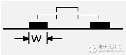
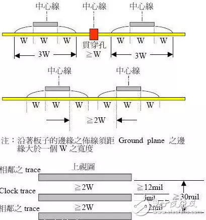
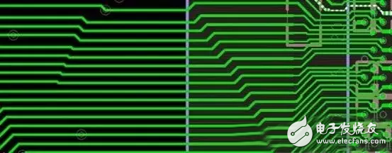
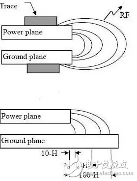
In the hardware development of Protel, the 3W and 20H principles in PCB design are very important. This article introduces the 3W principle, the 20H principle, and the five-five rules. These are worth learning. 3W principle: Here 3W is the distance between the line and the line is maintained at 3 times the line width. In order to reduce crosstalk between lines, it should be ensured that the line spacing is large enough. If the line center distance is not less than 3 times the line width, 70% of the line electric fields do not interfere with each other, which is called 3W rule. To achieve 98% of the electric field does not interfere with each other, the 10W rule can be used. For EMI. 20H principle: It refers to the distance between the power layer and the ground layer within 20H, and of course to suppress the edge radiation effect. Electromagnetic interference is radiated outward at the edge of the board. The power plane is retracted so that the electric field is only conducted within the range of the ground plane. Effectively improved EMC. If the internal contraction is 20H, 70% of the electric field can be confined to the grounding edge; if it is retracted by 100H, the electric field of 98% can be limited. For EMC. 1. The 20H principle in PCB design? The "20H rule" is adopted to ensure that the edge of the power plane is at least 20 times smaller than the edge of the 0V plane and equal to the layer spacing between the two planes. (1) This rule is often required as a side-shooting emission technique (suppression of edge radiation effects) from the 0V/power plane structure. However, the 20H rule will only provide significant results under certain conditions. These specific conditions include: 1. The rise/fall time of current fluctuations in the power bus is less than 1 ns. 2. The power plane is on the internal level of the PCB, and the upper and lower layers adjacent to it are 0V planes. The two 0V planes extend outward at least 20 times the distance between their respective planes from the power plane. 3. The power bus structure does not resonate at any frequency of interest. 4. The total derivative of the PCB is at least 8 layers or more. Question: Are these specific conditions sufficient or necessary? If the internal contraction is 20H, 70% of the electric field can be confined to the grounding edge; if it is retracted by 100H, the electric field of 98% can be limited. The 20H principle means that the edge of the power layer is at least 20 times smaller than the edge of the formation to reduce the edge radiation effect; Retraction 20H limits the electric field by 70%, and retraction 100H limits the electric field by 98%. Five-five rules: Printed board layer selection rules, that is, the clock frequency to 5MHz or pulse rise time is less than 5ns, the PCB board must use multi-layer board, which is a general rule, sometimes based on cost and other factors, using double-layer board In the case of a structure, it is preferable to use one side of the printed board as a complete ground plane layer. Off-Grid Solar System,Solar Hybrid System,Dc Solar Power System,Solar Home Power System JIANGSU BEST ENERGY CO.,LTD , https://www.bestsolar-group.com


