This article refers to the address: http://
In recent years, the most interesting event in the field of lighting is the rise of semiconductor lighting. In the mid-1990s, Nakamura and others of Japan Nichia Corporation broke through the key technologies for manufacturing blue-light digital tubes through unremitting efforts, and developed a technology to produce white light sources by using fluorescent materials to cover blue LEDs. In the digital tube industry chain, it is mainly divided into upstream semiconductor substrate growth, midstream chip manufacturing and downstream digital tube packaging technology. For the entire digital tube device, the packaging process is a very important part, mainly to complete the output electrical signal, protect the normal operation of the die, so that it is not subject to mechanical, thermal, humid and other external impacts, and has the function of outputting visible light, ie It meets the design and technical requirements of both electrical parameters and optical parameters. It can be seen that the packaging process has become a key factor restricting the use and performance of digital tube devices. For the development and production of white light digital tubes, the packaging process has more important significance.
China began to develop LED digital tube technology in the 1980s. By the 1990s, the LED packaging industry had developed to a certain extent, but the overall scale of the enterprise was small and the technological level was not high enough. This situation restricted the development of the industry, many There is no breakthrough in the technical bottleneck, and there is an urgent need for a better breakthrough in LED packaging technology to open up a new digital tube market share.
1 The realization of white light is based on the principles of luminescence and colorimetry, and there are many solutions for realizing white light digital tubes. The solution for developing earlier and industrialized is to apply phosphor on the digital tube chip to realize white light emission.
The digital tube uses phosphor to achieve white light. The following three schemes develop rapidly: a yellow phosphor that can be excited by blue light is applied on the blue chip, and the blue light emitted by the chip complements the yellow light emitted by the phosphor to form white light; The green chip is coated with green and red phosphors, and the blue light emitted by the chip is combined with the green light and the red light emitted by the phosphor to obtain white light; the phosphor of three primary colors or multiple colors is coated on the violet or ultraviolet chip, and the phosphor is used. The chip emits long-wave ultraviolet light (370-380 nm) or violet light (380-410 nm) to excite the phosphor to achieve white light emission. The following mainly introduces the mechanism for realizing white light based on the first scheme.
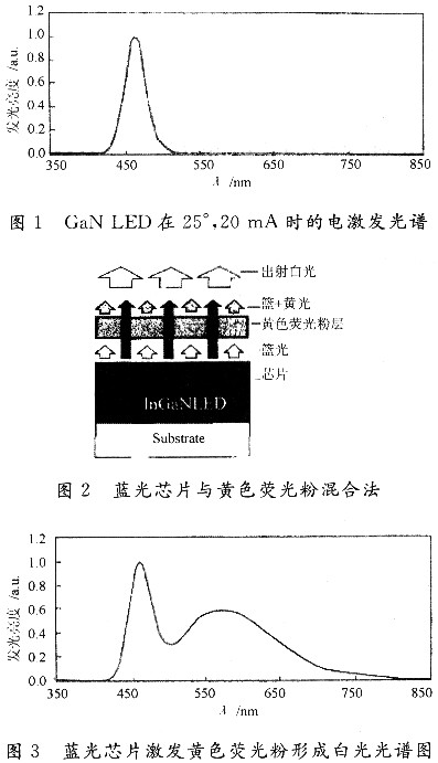
Blue light emitted by a GaN-based blue chip with a wavelength of 460 to 470 nm is used as a basic light source (Fig. 1 shows an electroluminescence spectrum of a blue chip in a greenhouse at a current of 20 mA), which is emitted by a GaN-based blue chip. A portion of the 460-470 nm blue light is used to excite the phosphor, causing the phosphor to emit yellow-green light and another portion of the blue light to be emitted through the phosphor. The yellow-green light emitted by the phosphor mixes with the transmitted portion of the GaN-based blue chip to form white light, that is, the mechanism of white light = blue + yellow, as shown in FIG. Figure 3 is a spectrum produced by a blue chip exciting yellow phosphor, producing yellow light, which is mixed with blue light to form white light. 
The two key parts of this method are the GaN-based blue chip and the fluorescent material used as a light conversion. The choice of GaN-based blue chip should not only consider the characteristics of the chip itself, but also the choice of fluorescent materials. The choice of fluorescent materials must meet the following two conditions:
(1) The excitation spectrum of the fluorescent material must match the emission spectrum of the selected blue chip. At present, GaN-based blue light chips with a wavelength of 460-470 nm are often used as the basic light source in the world, so that the excitation spectrum of the fluorescent material is required to be 460-470 nm, which can ensure higher light conversion efficiency; emission spectrum of fluorescent materials .
(2) The emission spectrum of the fluorescent material and the emission spectrum of the blue chip can be matched to white light. It can be seen from the CIEl931 color coordinate diagram that if it is desired to match white light, the emission spectrum of the fluorescent material should be around 555 nm. Based on the above technical requirements, YAG:Ce3+ light conversion materials are commonly used.
Because this method uses a single chip and a single kind of phosphor, the YAG:Ce3+ phosphor is mainly used for high conversion efficiency, easy to operate, and has no ultraviolet component, and will not cause ultraviolet radiation pollution. It is currently making a white light digital tube. The main direction.
2 Digital tube packaging technology The key to the quality of digital tube is in the package. Packaging technology plays a vital role in the performance and reliability of digital tubes. Poor quality packaging can lead to serious loss of photon loss of digital tube, low luminous flux and light efficiency, uneven light color, and short service life. The typical white digital tube structure currently developed is difficult to adapt to the requirements of the illumination source. The resin and optical structure for packaging need to adopt new design ideas, new processes and new materials, and the process is perfect, suitable for the development of solid illumination sources. While inheriting its original excellent performance, it is more important to abandon the old framework and innovatively introduce new white light digital tube packaging technology with its own characteristics.
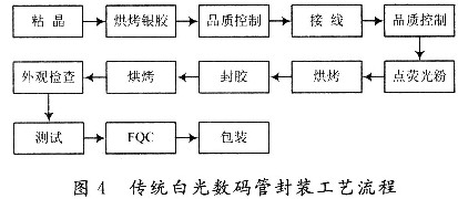
2.1 Problems Existing in Traditional Processes The following problems exist in the traditional packaging process (Figure 4 shows the traditional process flow chart). The choice of potting material and the effect of sealing process on the light effect parameters of digital tube. In the process of using the digital tube, the loss caused by the photon generated by the radiation composite mainly includes three aspects: the internal structural defects of the chip and the absorption of the material; the reflection loss due to the difference in refractive index of the photon at the exit interface; The angle is greater than the critical angle of total reflection causing total reflection loss. Therefore, a lot of light cannot be emitted from the chip to the outside. By coating a surface of the chip with a relatively high refractive index transparent layer (potting glue), since the glue layer is between the chip and the air, the loss of photons at the interface is effectively reduced to improve the light extraction efficiency. 
Currently used potting compounds include epoxy resin and silica gel. The inherent disadvantages of epoxy resins are poor impact damage resistance, poor toughness, and low heat resistance (less than 170 ° C). Because of its high light transmittance, large refractive index, good thermal stability, low stress and low hygroscopicity, silica gel is superior to epoxy resin. However, studies have shown that the performance of silica gel is greatly affected by the ambient temperature. As the temperature increases, the thermal stress inside the silica gel increases, causing the refractive index of the silica gel to decrease, thereby affecting the luminous efficiency and light intensity distribution of the digital tube. The traditional method of phosphor coating is to mix the phosphor with the potting compound and then apply it to the chip. Due to the inability to accurately control the thickness and shape of the phosphor coating, the color of the emitted light is inconsistent, and blue or yellowish light appears.
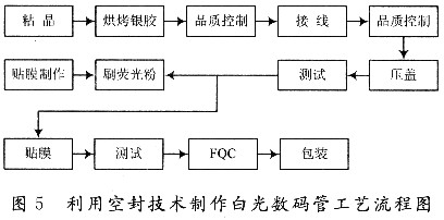
2.2 Air -sealing technology As a new process technology for digital tube packaging, air-sealing technology is developed on the basis of the original technology. On the basis of the traditional digital tube process, the two production steps of epoxy resin potting and high temperature curing are removed. After the circuit board that has been solidified and connected to the wire is sleeved, the cover is molded. Finally, a scattering film is attached to the display surface to obtain the white light required for production (Fig. 5 is a process flow diagram for manufacturing a digital tube by using an air-sealing technique). These problems can be solved by using the air-sealing technology process: 
(1) The production of digital tubes by air-sealing technology eliminates the production process of sealing and baking, and relieves the difficulty of selecting sealing materials in traditional processes.
(2) Replacing the point phosphor process with the brush phosphor process technology, solving the problem of the precision of the spot phosphor in the traditional process.
The use of new technologies to produce digital tubes must address the following technical issues:
(1) Using a silk screen printing technique, screen printing, and electronic inkjet printing to produce a special phosphor film. When making fluorescent film, it is necessary to pay attention to some problems that affect the quality when printing with silk screen printing. Firstly, when the static screen is kept at a certain distance between the screen and the substrate, the size of the distance has a great influence on the quality of the silk screen, and the distance is also The amount of wire mesh elongation is related. Under normal conditions, that is, when the distance is optimal, the screen can immediately be ejected from the substrate during the silk screen process. The cohesion of the print itself must be overcome to overcome the tension between the print and the substrate. Secondly, the angle between the squeegee and the substrate generally varies between 50° and 55°. Theoretically, the printed pattern is larger than 45°, and the printed pattern is less than 45°. Repeated printing occurs, both of which reduce the accuracy of silk screen printing. Master the correct squeegee angle between the squeegee and the substrate. Theoretically, the angle between the squeegee and the substrate is required, that is, the right angle edge of the squeegee is 45°. To ensure the condition of contact between the line and the substrate, it is impossible to produce reprinting and plucking, and to ensure that the pattern is smooth and not smeared. side. In short, it is required to make a special phosphor film to ensure the uniformity of thickness and density of the screen during printing.
(2) Research and development of digital tube air-sealing technology. Anti-oxidation and tempering treatment of aluminum wire, uniformity of illuminating reflection of digital tube. In air, the oxide layer of the low-temperature treated aluminum wire material still contains a considerable amount of carbon, and the oxidation reaction advances to the inside faster. The material treated at high temperature completely decarburizes the oxide layer and forms a dense sintered layer. While hindering the progress of the oxidation process, the increase in the depth of the oxide layer is slow. With a suitable surface coating, a protective layer can be formed over a wide temperature range from low to high temperatures to prevent continued oxidation of the carbonaceous material. After the aluminum wire is treated with oxidation, the oxidation time exceeds 100,000 hours, and after the aluminum wire is subjected to tempering treatment, the tensile force is at O. 1 V or more. The optimized design of the reflection tube and the light exit channel of the digital tube makes the brightness error of the digital tube pen segment less than or equal to 10%.
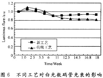
2.3 Influence of two different processes on optical parameters The digital tubes produced by the two processes have certain differences in luminous flux and digital tube life. Since the digital tube made by the traditional process adopts a potting material, the material layer is between the chip and the air, thereby effectively reducing the loss of photons at the interface and improving the light extraction efficiency. However, since the digital tube made by the new process does not use the potting layer, only the transparent insulating glue coated on the core and the bottom plate is used to improve the light-emitting efficiency, and the photon is directly emitted outward. Due to the emission and refraction of the light, part of the photons cannot reach the outside. , causing photon loss. Therefore, the digital tube produced by the new process in the initial stage has a low luminous flux. Due to the thermal conductivity of the potting material and photon absorption, the lifetime and luminous flux decrease during long-term high-temperature operation. Figure 6 is the experimental results of the effects of two packaging technologies on the light decay of digital tubes when subjected to high temperature aging. It can be seen that the products produced by the new process are significantly superior to the traditional craftsmanship in terms of luminous flux and lifetime. 
2.4 The actual economic value of the digital tube produced by the air-sealing technology process (1) The process of producing the white-light digital tube epoxy sealant by the traditional process is eliminated, and the potting material is not used, which not only saves the raw materials, but also improves the product. reliability;
(2) The film technology replaces the high-temperature curing sealant, which can save energy; the cost of the new process product is about 50% of the cost of the traditional process product, and the price advantage is obvious.
The white light digital tube developed by the air sealing technology adopts a film coating process to avoid the contamination of the epoxy resin. Eliminating the high-temperature sealing process, the basic energy saving of manufacturing products is more than half of the original, and the cost is significantly reduced, which is conducive to expanding market competitiveness.
3 Conclusion The white light digital tube currently produced is mainly obtained by coating a yellow phosphor layer on a blue chip and mixing it with blue light and yellow light. The matching of the chip and the phosphor is an important factor affecting the electrical, optical performance and stability of the device. For the entire digital tube device, the packaging process is a very important part, mainly to complete the output electrical signal.
The protection die works normally, so that it is not subjected to mechanical, thermal, humid and other external impacts, and has the functions of outputting visible light, that is, design and technical requirements having both electrical parameters and optical parameters. In this paper, the implementation method of white light digital tube based on air-sealing technology is given. The performance of the original digital tube is improved and the cost is greatly reduced.
Research on Implementation Method of White Light Digital Tube Based on Air Seal Technology
0 Preface