Incremental encoders provide speed, direction and relative position feedback by generating a stream of binary pulses proportional to the rotation of a motor or driven shaft. Lander offers both optical and magnetic incremental encoders in 4 mounting options: shafted with coupling, hollow-shaft, hub-shaft or bearingless. Single channel incremental encoders can measure speed which dual channel or quadrature encoders (AB) can interpret direction based on the phase relationship between the 2 channels. Indexed quadrature encoders (ABZ) are also available for homing location are startup.
Incremental Encoder,6Mm Solid Shaft Encoder,Hollow Rotary Encoder,Elevator Door Encoder Jilin Lander Intelligent Technology Co., Ltd , https://www.jilinlandermotor.com
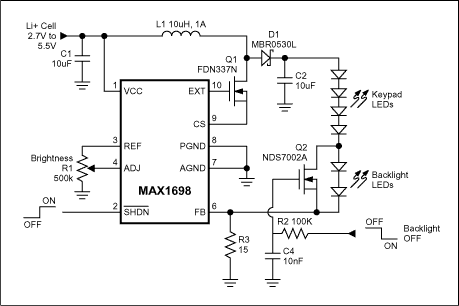
A design in which the display is backlit (or frontlit) for extended periods needs an efficient circuit that drives the LEDs with a controlled current, and eliminates the wasted power associated with current-limiTIng resistors. A switch-mode boost design that regulates current instead of voltage accomplishes this purpose (Figure 1). 
Figure 1. When this circuit turns off the backlight LEDs, the keypad LEDs remain on with no change in intensity.
Because all LEDs are connected in series, they all receive the same current without need for ballasTIng resistors. IdenTIcal currents help achieve uniform intensity. And because the output current is small (20mA in this case), the output filter capacitance (C2) can be smaller than for a load consisTIng of parallel-connected LEDs. The Figure 1 circuit's conversion efficiency (90%) provides a distinct power-saving advantage over resistor-limited and linearly regulated designs.
It might appear that a series-LED connection is not suitable for applications in which some (but not all) LEDs must be turned off. That capability is sometimes needed in a cell phone for which the display is off but the keypad remains lit, or in a handheld PDA that needs to play a sound file while maintaining illumination in the buttons but not the display. Actually, switching off individual LEDs or groups of LEDs is not a problem, even when all are driven in series.
Applying a logic-high level to the gate of a simple MOSFET switch (Q2) turns off a subset of LEDs (backlight LEDs in this case) by shunting their current. The remaining (keypad) LEDs remain on, and their intensity remains constant because their current is regulated by IC1, which senses the voltage across R2 (300mV at full brightness). When turning the LEDs on and off, an RC network at the gate of Q1 (R2, C4) slows the load changes sufficiently to prevent transient changes in the LED drive current. Other features include adjustable intensity via the ADJ pin, and full shutdown via the SHDN-bar logic input.
A similar version of this article appeared in the April 12, 2001 issue of EDN magazine.
Single tube controls the second LED array in switch mode LED backlight-Single F
White-LED backlights are gaining acceptance because they offer higher reliability and simpler drive circuitry than those based on CCFL and EL technology. As a result, the white-LED backlight is increasingly common in PDAs, cell-phones, digital cameras, and other portable devices.