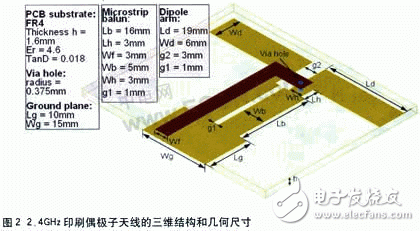
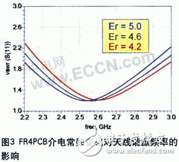
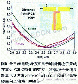
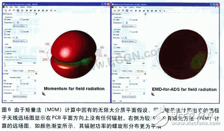
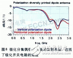
Electromagnetic field and electromagnetic field and circuit co-simulation of 2.4 GHz polarization diversity printed antenna with switching circuit. By using polarization diversity technology, wireless local area network (WLAN) antenna with good receiver performance can be fabricated with low cost PCB substrate. . This article describes how to use the latest 3D electromagnetic field (EM) simulation tools to design and simulate a pair of 2.4 GHz orthogonally polarized printed dipole antennas while predicting surface currents and associated far-field radiation patterns. Unlike many current themes of the same subject, this article discusses how to consider the effects of baseband circuit components used for antenna polarization switching by using EM circuit co-simulation. Using the methods described in this paper, designers can directly motivate antennas from linear or nonlinear circuit simulations without having to manually perform data transfers. Consumer wireless applications require antennas to be installed concealed in wireless products and must be low cost and high performance. The following example describes how to meet the above requirements for 2.4 GHz WLAN applications by printing a bi-orthogonal dipole antenna on an FR4 PCB board. When the PCB board is placed vertically, the vertical or horizontal dipole antenna will preferentially transmit and receive vertical or horizontally polarized signals, as shown in Figure 1. This polarization diversity technique can be used to reduce the effects of multipath reflections and interference on the WLAN network by establishing circuits in the antenna unit that detect and switch stronger signals. The design and analysis of this kind of antenna has been described in detail in some literatures, so this article will use the electromagnetic field (EM) simulation to quickly analyze the characteristics of the antenna, and then use the electromagnetic field and circuit co-simulation technology to analyze the impact of the switching circuit on the antenna performance. . Rapid analysis of antenna design using electromagnetic field simulation Figure 2 shows the structure and geometry of a dipole antenna. Accurate simulations were performed using the Agilent EEsof EDA's Momentum 3D planar electromagnetic field simulator antenna structure, which was consistent with accepted data. The Momentum 3D planar electromagnetic field simulator runs on a typical laptop (HP xw4400 Intel Dual Core 6600 2.4GHz WinXP 64bit 2GB RAM) with a simulation time of one minute. Thanks to this fast simulation, we can quickly analyze the characteristics of the antenna when the variables such as geometry or material parameters change. Figure 3 shows the effect of the change in dielectric constant of FR4 between 4.2 and 5.0 on the resonant frequency of the dipole antenna. Here we note that the higher the dielectric constant, the lower the resonant frequency. This result is unexpected, as the wavelength in the substrate material is reduced relative to the increase in dielectric constant, and the dipole antenna itself has a larger electrical size. These changes are often present when designing products with low manufacturing costs, and it is especially important to consider these factors. The antenna design can be further understood by looking at the effects of the changes in the geometry shown in Figure 4 on the antenna surface current. Surface current maps are useful for diagnosing mismatches or undesired sources of coupling. The current density is represented by multiple colors and animated by a 360° scan of the current phase. Now, it can be seen how the current is introduced into the adjacent structure or where it causes unwanted resonances for further correction. This is much more precise and efficient than traditional heuristics for machining and adjusting boards or for continuously cutting and pasting boards. The Moment Method (MOM) simulation technique used in Momentum assumes that the media plane is infinite. Most applications approximate this condition. In cases where finite media effects must be considered (eg, when the printed dipole is very close to the edge of the PCB), the finite element method (FEM) can be used for analysis using a full 3D electromagnetic field simulation tool. Figure 5 shows the simulation using the Electromagnetic Design System (EMDS) developed by Agilent EEs of EDA. The dipole antennas were placed one after another at 5 mm and 2 mm from the edge of the PCB. It was found that the resonant frequency occurred at approximately 100 MHz. Offset. The far field radiation pattern of the dipole antenna predicted by Momentum and EMDS is compared in Figure 6. Since EMDS does not need to assume the condition of the infinite PCB dielectric plane in the calculation process, its predicted far-field map is more accurate than the far-field graph predicted by the moment method. The result of the moment method simulation shows the assumed infinite PCB plane. There is no radiation in the direction). Synergistic and synergistic optimization of circuit components and antennas In order to make full use of the polarization diversity technique, the dipole antenna can be turned on and off by using a switching circuit composed of a pin diode to be connected to the dipole antenna. In the meantime we must consider: These factors can be analyzed by performing electromagnetic field and circuit co-simulation using Momentum integrated in the Advanced Design System (ADS) platform. Figure 7 shows the co-simulation setup of a double dipole antenna and switching circuit where the PIN diode after each dipole antenna is biased using a +5V or -5V control voltage to achieve polarization selection. Figure 8 shows the S11 reflection coefficient obtained from the common feed of two double dipole antennas. From now on, if it is necessary to optimize the resonant frequency or S11 matching of the dipole antenna by adjusting the geometry of the dipole antenna and changing the parameters of the switching circuit, the electromagnetic field and circuit co-simulation can be performed in the ADS. In a software-defined radio environment, where a single antenna must be able to operate at different frequencies and bandwidths, similar techniques can be used to design an adaptive antenna matching or beamforming network under DSP control. It also facilitates an adaptive switching circuit that switches the capacitor matrix. When the handset is at a different distance from the user, the adaptive circuit tracks the changing antenna characteristics by switching between different capacitors. ZTTEK Batteries, For 5G backup base station .Customize the lithium ion battery packs according to the application and product requirements of the customers. 48V200Ah Lithium Ion Battery,Lifepo4 Battery 48V 200Ah,Rechargeable Battery 48V 200Ah,48V 200Ah Lifepo4 Battery Pack Jiangsu Zhitai New Energy Technology Co.,Ltd , https://www.zhitainewenergy.com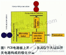
Lithium ion battery integration requires a special set of skill and expertise to optimize the performance and battery life.ZTTEK Batteries , using the most advanced technology delivers the best quality battery packs.
Our batteries are safe to use, better performance, higher shelf life and a very low maintenance cost.