Detailed analysis of ABB robot programming
1. ABB robot Pdisp track offset use
1) If there are two products in the figure below, the product track on the right has been completed. The product on the left is estimated to be the same. How to quickly generate the left track (the product on the left may have translation and rotation)
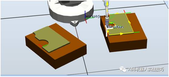
2) Complete the path on the right to teach Path_30, as shown above. The starting point is Target_20.
3) Complete the teaching of the left starting point, which is Target_ref_start, as shown below.
Note: If the product track on the left side is rotated, the attitude of the taught Target_ref_start relative to the left product should be consistent with the attitude of Target_20 relative to the right product (the left product is rotated by 30°, and the taught angle z is also rotated by 30°). )
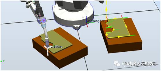
4) Insert instructions are as follows
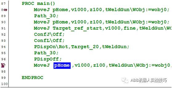
MoveJ pHome, v1000, z100, tWeldGun\WObj:=wobj0;//Move to Home location
Path_30; / / run the product track on the right
MoveJpHome, v1000, z100, tWeldGun\WObj:=wobj0;//Back to Home
MoveJTarget_ref_start, v1000, fine, tWeldGun\WObj:=wobj0;//Go to the left product starting point
ConfJ\Off;//Because the offset is used, the axis configuration monitoring is turned off. Otherwise, it is possible to use the original configuration parameters to cause the position to go and the error is ConfL\Off; //Because the offset is used, the axis configuration monitoring is turned off, otherwise it is possible to use The original configuration parameters cause the location to go wrong and report an error.
PDispOn\Rot, Target_20, tWeldGun; / / set the deviation of the current position and Target_20 (including translation and rotation), because the robot stops at the start of Target_ref_start, that is, set the overall offset relationship between the left and right tracks. Use ot to mean both translation and rotation. If you don't use ot, only use panning, rotation is not calculated
Path_30; / / run the original trajectory, at this time the trajectory reference coordinate movement relationship, the robot actually goes to the left product trajectory
PDispOff; / / track completion, close the translation relationship
MoveJ pHome, v1000, z100, tWeldGun\WObj:=wobj0;
2. Single station multiple booking procedure
1) The robot has the following procedures.
2)
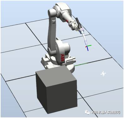
3) The process is as follows:
The robot waits at home. Someone pressed the di signal and the robot started executing. Labor can make multiple appointments at once, that is, if the manual is pressed 3 times, the robot executes three times.
4) We do this by interrupt.
5) The meaning of the interruption is that the robot background is constantly scanning (like PLC), and the robot foreground motion does not conflict. The real-time scan of the signal in the background will execute the set interrupt program, there is no motion command in the interrupt program, the front-end robot does not stop, does not affect the motion.
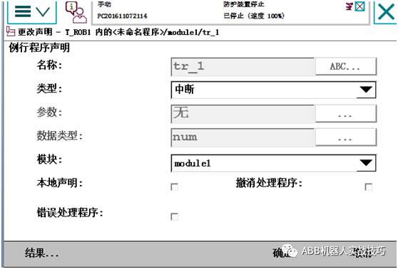
6) Create a new routine, named tr_1, note: type select interrupt (trap)
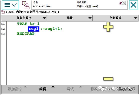
7) Enter the interrupt program, insert the instruction as follows, that is, when the robot executes the interrupt program, add 1 to the reg1 record count.
8) Enter the main program, set the interrupt and the corresponding io signal
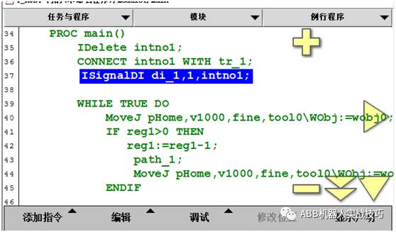
Line 37 means that whenever the di_1 signal 0 changes to 1, it will trigger the execution of the tr_1 interrupt routine, that is, set flag1 to true.
The 35-37 line program can be run once, similar to setting the switch, no need to run repeatedly.
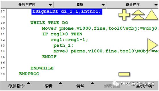
9) The main procedures are as follows. That is, if reg1=0, the robot waits at home
More videos to explain, you can also log in
3. Create a socket connection for two robots in robotstudio
1) What is socket communication?
Is TCP/IP communication, no protocol, called socket in Microsoft environment
2) What can socket communication do?
Can send and receive data, including sting strings, byte arrays, etc.
3) What options are needed to create a socket robot?
The robot needs the 616-1 PC-INTERFACE option
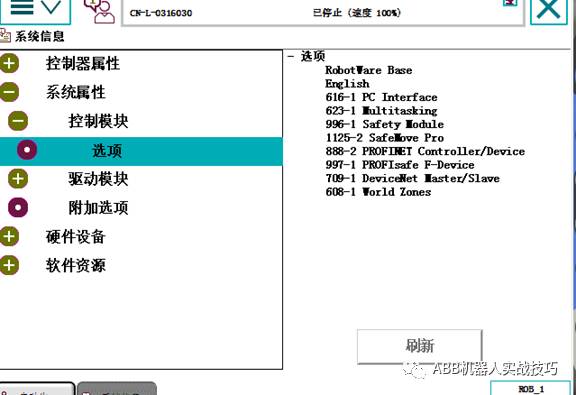
4) Which network port is plugged into the socket communication network?
Service port (IP fixed: 192.168.125.1) or Wan port can be (can be set by yourself)
5) Create an instance of the client
Usually the robot communicates with the camera, and the robot acts as the client.
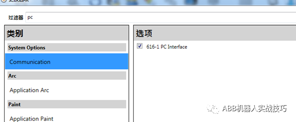
1) Create a new robot system, pay attention to the pc-interface option when building the system.
 2) In order to avoid the previous connection is not closed, insert the socketclose instruction first, and the subsequent socket1 is the variable of the newly created socketdev type.
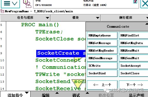
3) After inserting create connection socketCreate
4) Insert to establish a connection SocketConnect, you need to develop the ip and port of the server, if it is connected to the computer and another virtual controller, ip is set to "127.0.0.1", the port is customized, it is recommended not to use the default 1025.
This step is that the robot will establish a connection with the server. If it is not established successfully, it will wait until it succeeds.
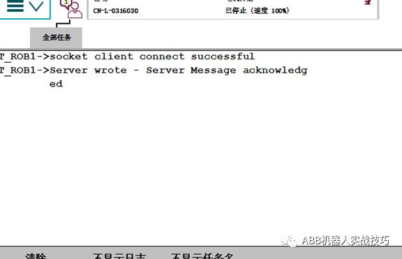
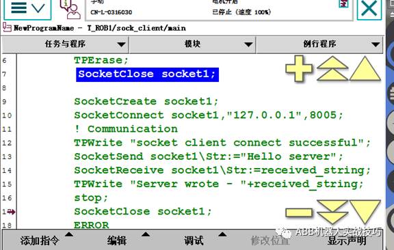 5) Test here, after the establishment is successful, insert the TPWrite instruction, you can see socetclinent connect successful in the teach pendant
6) Next, you can send and receive data. Here, the client sends the data to the server first, and then accepts the data sent by the server.
7) SocketSend can send string or byte array, you can choose different optional variables
8) After the sending is completed, the client accepts the data sent back by the server and writes the screen.
6) The following is a server side example
1) Re-create a workstation, don't forget to add pcinterface option when creating
2) As a server, the robot needs to create 2 socketdev variables
3) In order to avoid the previous connection is not closed, it is also recommended to first socketclose
4)
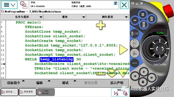
5) Then create socketCreatetemp_socket server-side socketdev
6) SocketBind is the ip and port to be bound to the socket to be monitored. If it is a virtual emulation, the ip is 127.0.0.1, and the port is customized (consistent with the client setting)
7) SocketListen for the robot server to monitor whether there is a client connection
8) socketAccept is to accept the client's connection
9) After the connection is established, the robot can perform an infinite loop, that is, it is always in the transmitting and receiving state.
10) Before the client program is sent to the client first, then the server is received first. 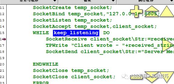
7) After the client and server are written, you can run it. Note that the server is running first, that is, the server robot is in the listening state. If it is connected, the two stations communicate with each other. The effect is as follows:
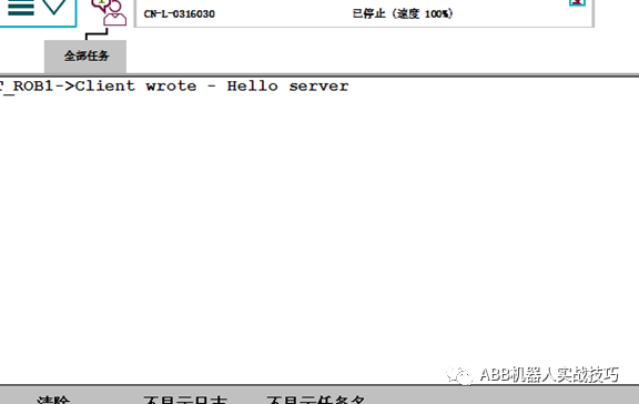
8) The message received by the server robot is as follows:
9) The message received by the client robot is as follows:
4. ABB robot double station reservation program
1) There are the following duplex production
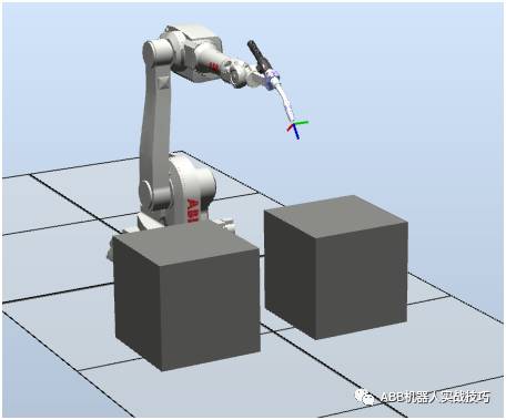
2) The process is as follows:
Manually finish the 1# station and press the button di_1 (the button does not hold, that is, the hand release signal is 0)) The robot welds the 1# station.
In this process, the 2# station is manually loaded and unloaded, and after completion, the reservation is completed by di_2 (that is, the robot does not need to wait for the 1# work).
After the robot finishes the 1# work, the robot automatically completes the 2# station because it received the di_2 reservation signal.
3) We do this through interrupts.
4) The meaning of the interruption is that the robot background is constantly scanning (like PLC), and does not conflict with the robot foreground motion. The real-time scan of the signal in the background will execute the set interrupt program, there is no motion command in the interrupt program, the front-end robot does not stop, does not affect the motion.
5) Create a new routine, named tr_1, note: type select interrupt (trap)
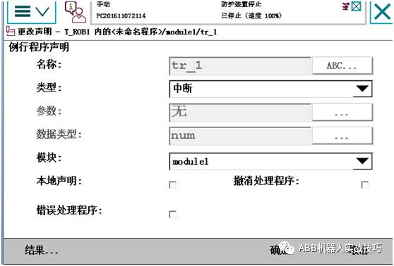
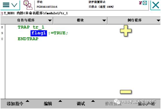
6) Enter the interrupt program, insert the instruction as follows, that is, when the robot executes the interrupt program, set the bool to true.
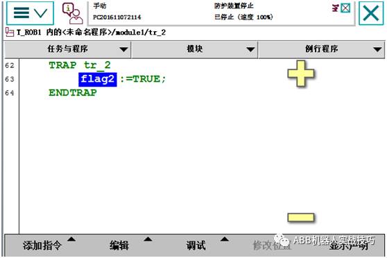
Similarly, set the second interrupt program
7) Enter the main program, set the interrupt and the corresponding io signal
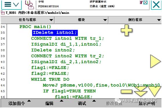
Line 37 means that whenever the di_1 signal 0 changes to 1, it will trigger the execution of the tr_1 interrupt routine, that is, set flag1 to true.
The 35-40 line program can be run once, similar to setting the switch, no need to run repeatedly.
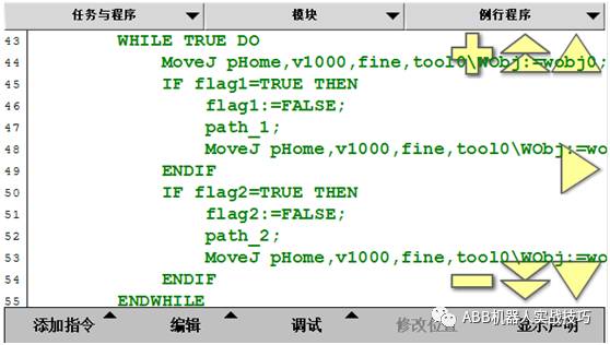
8) The main procedures are as follows. That is, if no one gives a di signal, the robot waits at the home.
9)
5. Socket transceiving data processing and extraction with camera communication
1) The camera usually sends a string to the robot, such as "1.23, 4.56, 7.89\0D", that is, x is 1.23, y is 4.56, z is 7.89, and \0D is used as the terminator. "," is used between data. Separated.
2) If the robot receives the above string, how do I extract the string and pay the variables deltaX, deltaY, and thetaZ?
3) Create a number of num variables to store process data, such as StartBit1, which means that the data of x starts from the first digit, Endbit1 indicates that the end of the data of x is the first digit, Lenbit1 represents the length of the x data, and s1 represents the extracted x. Value string
4)
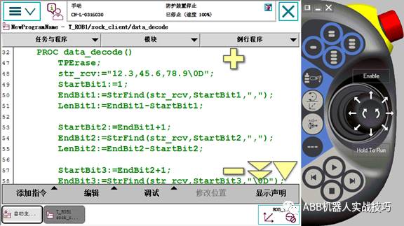
5) First assume that the first digit of x is 1, and the value of Startbit1 is set to 1.
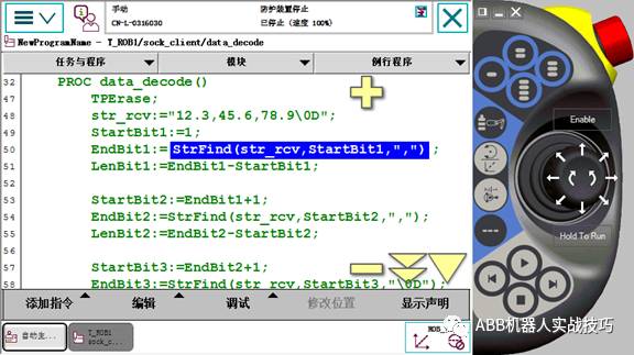
6) Insert the function strfind, find the first "," in the first few bits, get the EndBit1 value
7) 
8) EndBit1 minus StartBit1 is the data length of x
9) Similarly, get information about y and theta
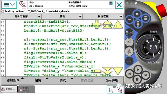
10) Extract the string from the start of StartBit1 to the end of LenBit1 through the StrPart function, that is, the string of the value of x
11)
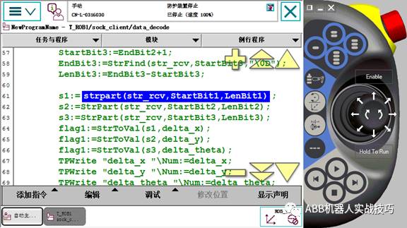
12) Similarly, get the string of y and z
13) Through the StrToVal function, convert s1 to num type, and pay to delta_x. The feedback value of StrToVal function is bool quantity, that is, the conversion success is true and unsuccessful is false.
14) Similarly, get delta_y and delta_theta
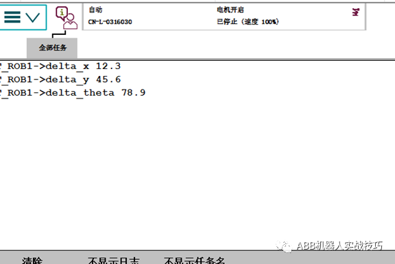
15) After successful, you can write a screen test, as shown below
6. How does ABB robots create arrays?
1) What is an array?
a collection of elements of the same data type arranged in a certain order
2) What is the use?
For example, create an array of robtarget type p_array, there are 10 points in p_array, you can use the following code after 10 positions, convenient and concise
FOR i FROM 1 TO 10 DO
MoveL p_array{i}, v500, z1, tool0;
ENDFOR
3) Which data types can create arrays
Arrays can be created for all data types
4) The maximum number of dimensions of the array?
ABB robot arrays up to 3D!
5) Is the array starting number 0 or 1?
it's 1
6) How to create
1) Program data
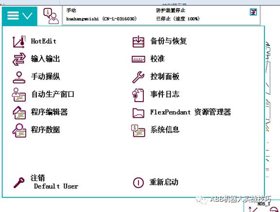
2) Select the type, such as Robtarget
3) New, set the name, dimension (example 1 dimension here), the number of elements in each dimension (for example, 10)
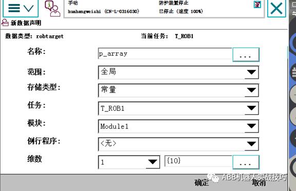
4) After creation, there is a p_array of 10 data.
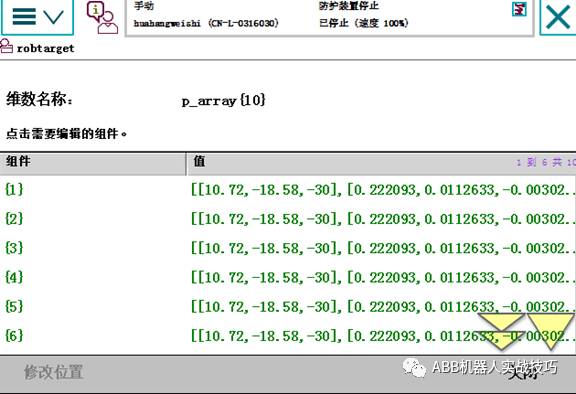
5) Modify the point, click on a line on the above picture, modify the position, that is, modify the position of an element in the array.
7. ABB robots create custom data types
1) What is the data type?
Such as robtarget, jointtarget, etc., together a series of related elements, similar structures
2) How to view the data type of the system
Robotstudio's command function data type
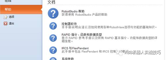
3) Can ABB robots customize the data type?
can
4) How to create a custom data type
Must be created at the top of the module, using the keywords RECORD and ENDRECORD
5) Examples are as follows:
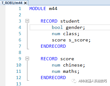
A data type is defined called student, which includes gender (bool amount), class (num), and score. The score is again a custom data type, including language and math scores.
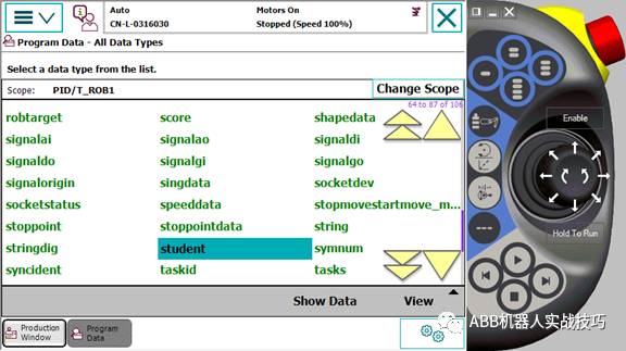
6) You can view this custom data type student in the program data.
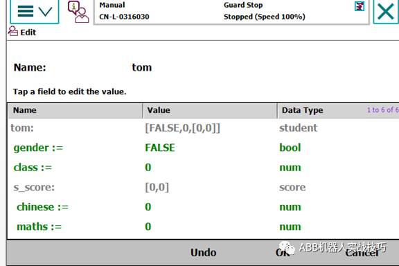
7) You can create a new variable, type is student, you can set the content
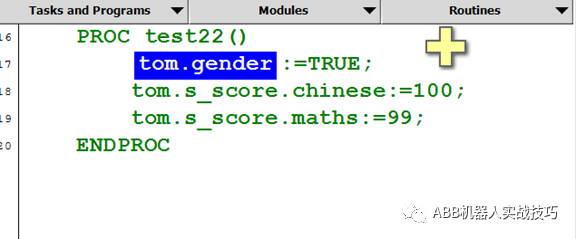
8) It is also possible to assign values ​​in the teach pendant, similar to p10.trans.x
8. ABB robot data storage type difference
CONST VAR PERS difference
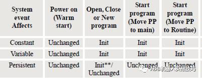
1) Any data of ABB robot has storage type, which is divided into constant CONST, variable VAR and variable PERS.
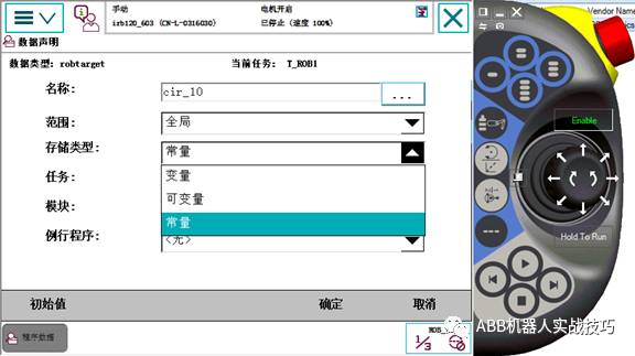
2) Constant CONST, that is, cannot be assigned in the program
3) Variables and variable variables can be assigned, the difference is as follows
Variable - has initial value and current value. When the open program is executed, the pointer is moved to the main, and the pointer is moved to the routine, the current value of the variable is initialized, that is, the value becomes the initial value.
Variable, only the current value. That is, any time a modification is made, its value is modified. When executing the open program, moving the pointer to main, and moving the pointer to the routine, the value is the current value and will not change.
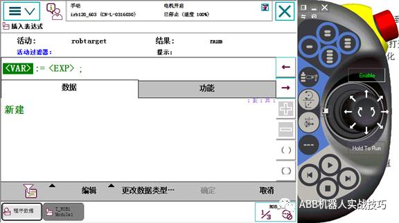
4) The default inserted robtarget storage type is const, which is a constant. At this time, it cannot be assigned (as shown in the figure below, even if the type is selected to robtarget or does not display the established robtarget)
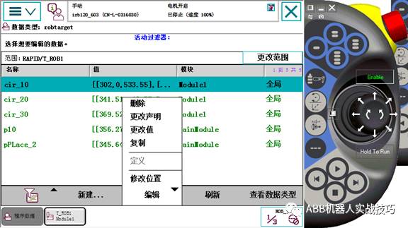
At this point, to the program data, find this data, edit-change declaration, modify to variable
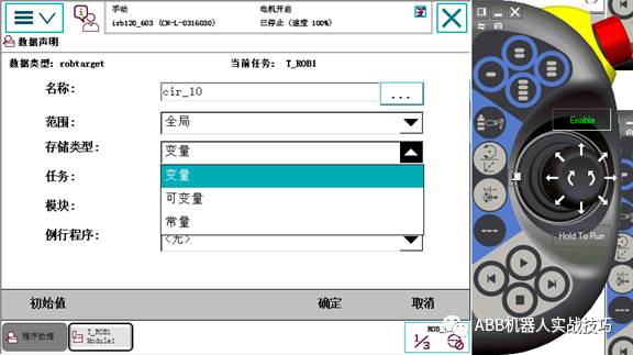 This point can be found when the assignment statement is inserted.
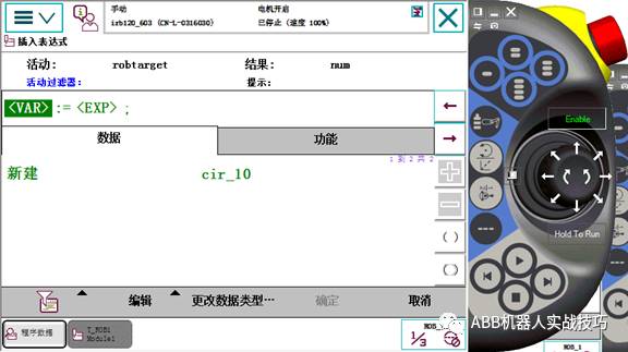
9. Create a routine with parameters
1) What is a parameter routine?
Routines can enter parameters that look like custom instructions when used
2) What is the use?
Easy to use, users don't care about the internal implementation process
3) How to create
1) New routine
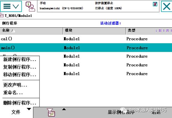
2) Set the name, click on the parameter, set the input parameters
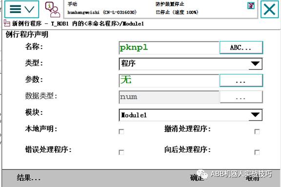
3) Add parameters, note that the data type on the right is the data type of the parameter. Here, for example, enter 2 robtargets.
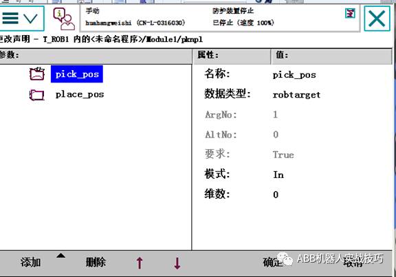
4) Click OK.
5) Add content according to your needs within the program
6) The routine with parameters can not be used directly, must be called, and the input parameters are as follows
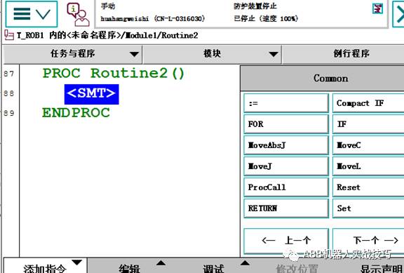 Use ProcCall
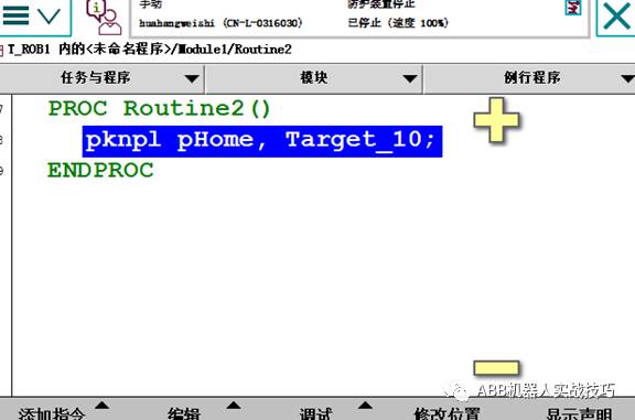
7) Here to create the pknpl instruction, the implementation function is to draw from the pHome position and place it in the Target_10 position.
PROCRoutine2()
Pknpl pHome,Target_10;
ENDPROC
PROCpknpl(robtarget pick_pos,robtarget place_pos)
MoveJoffs(pick_pos,0,0,30), v500,z1,tool0;
MoveL pick_pos, v500, fine, tool0;
Set do1;
MoveLoffs(pick_pos,0,0,30), v500,z1,tool0;
MoveJoffs(place_pos,0,0,30), v500,z1,tool0;
MoveL place_pos, v500, fine, tool0;
ReSet do1;
MoveL offs(place_pos,0,0,30), v500,z1,tool0;
ENDPROC
10. ABB robot creates palletizer
1) What is the code?
Regular mobile robot for grabbing and placing
2) How to make a simple palletizer
Set the workpiece coordinate system, tool, teach the first pallet placement point, the spacing and number in the xyz direction can be set
3) How to create
Create m_pallet module
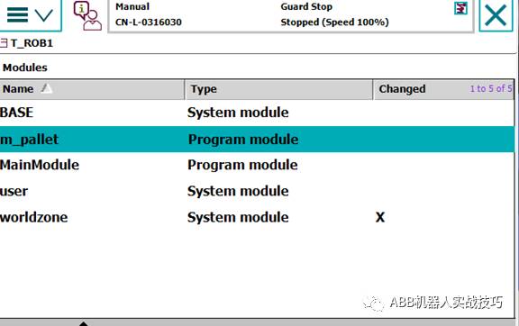
Create two routines
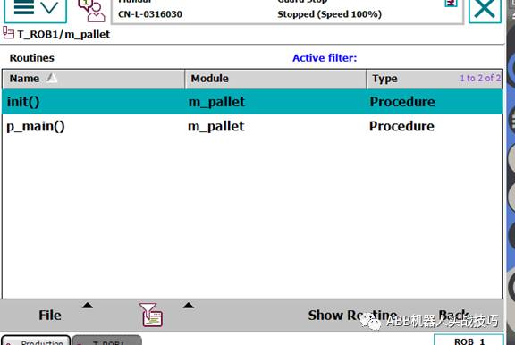
In the init program, set the number of xyz directions and the spacing between the directions
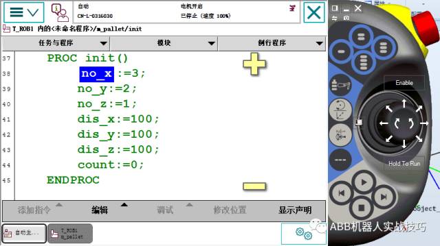
In the p_main program, create the robot to move to the pHome point, the pPick position (crawl position), and the first placement point pPlace_ini
The palletizing is performed through a three-layer for loop. The example program is first x direction, then y direction, then z direction
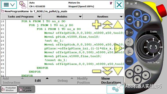
The offset is as follows:
pPlace:=offs(pPlace_ini,(i-1)*dis_x,(j-1)*dis_y,(k-1)*dis_z);
11. Create a regular robot to rotate Robtarget
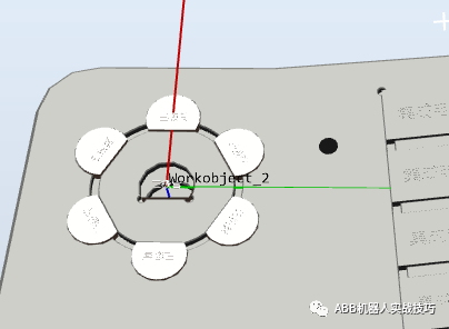
1) If there are 6 product locations to be drawn as shown in the figure above, how can I create the most quickly? (Pure teaching? Naive, too physical.)
2) As shown in the figure below, we can find that position 1 is the same as position 0. No. 1 is a radius offset from No. 0, and position 2-6 is also a radius offset from 0. 2 The posture of the -6 is toward the center of the circle. Since there are 6 in the figure, starting from the 2nd, each point is rotated by 60° with respect to the 1st.
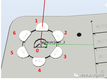
3) Is it possible to teach the position of the 0th point and know the radius (if you don't know it, you can measure it yourself), you can automatically calculate the other 6 points without teaching? The answer is of course ok! ! !
4) Because of the coordinate system offset and rotation, the Tool and workpiece coordinate system should be done well.
5) Create the tool gripper_dual, assuming the z direction is 100, the tool's Z direction is the tool extension direction
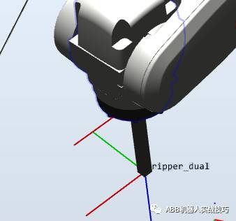
6) Create a coordinate system as shown below. The center of the circle is in the middle, and the direction from 0 to 1 is X, y. The workpiece coordinate system Z in the figure below is facing down (means the right-hand rule). This is mainly created for the convenience of calculation
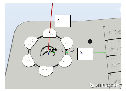
7) In the workwobject2 coordinate system, the gripper_dual tool, teach the intermediate product position Target_center, then the tool Z must be perpendicular to the product plane, that is, the tool's Z is facing down. (In fact, just use the attitude of this point and z, the xy of this point is 0, because this point is at the origin of the workobject2 coordinate system, that is, xy is 0)
8) Set the distance from the center of the circle to the first product (ie radius radius), here for example 21.45mm
9) We assume that the first position is called Target1, then in the workobject2 coordinate system
Target1:=Target_center;! Let Target1 position and posture equal to Target_center
Target1.trans.x:=radius*cos(60*0);! Recalculate the position of x
Target1.trans.y:=radius*sin(60*0);! Recalculate the position of y
Target1:=RelTool(Target1,0,0,0\Rz:=0*60);! After obtaining the calculated positions x and y, tcp is rotated 60° around the Z of the tool.
10) Through the above example, the Target1 position is obtained, and the attention is in the workobject2 coordinate system.
11) With the test and other processes, it is relatively simple to complete the calculation and movement of 6 positions, as follows
PROC main()
Radius:=21.45;
Count1:=1;
WHILEcount1<7 DO
rHome;
Cal;
Routine1;
Count1:=count1+1;
ENDWHILE
ENDPROC
PROC routine1()
MoveJoffs(Target_temp,0,0,-30), v500,z1,gripper_dual\WObj:=Workobject_2;
MoveLTarget_temp, v500, z1, gripper_dual\WObj:=Workobject_2;
WaitTime 1;
MoveLoffs(Target_temp,0,0,-30), v500,z1,gripper_dual\WObj:=Workobject_2;
ENDPROC
PROC cal()
Target_temp:=Target_center;
TEST count1
CASE 1:
Target_temp.trans.x:=radius*cos(60*(count1-1));
Target_temp.trans.y:=radius*sin(60*(count1-1));
Target_temp:=RelTool(Target_temp,0,0,0\Rz:=(count1-1)*60);
CASE 2:
Target_temp.trans.x:=radius*cos(60*(count1-1));
Target_temp.trans.y:=radius*sin(60*(count1-1));
Target_temp:=RelTool(Target_temp,0,0,0\Rz:=60);
CASE 3:
Target_temp.trans.x:=radius*cos(60*(count1-1));
Target_temp.trans.y:=radius*sin(60*(count1-1));
Target_temp:=RelTool(Target_temp,0,0,0\Rz:=120);
CASE 4:
Target_temp.trans.x:=radius*cos(60*(count1-1));
Target_temp.trans.y:=radius*sin(60*(count1-1));
Target_temp:=RelTool(Target_temp,0,0,0\Rz:=180);
CASE 5:
Target_temp.trans.x:=radius*cos(60*(count1-1));
Target_temp.trans.y:=radius*sin(60*(count1-1));
Target_temp:=RelTool(Target_temp,0,0,0\Rz:=-120);
CASE 6:
Target_temp.trans.x:=radius*cos(60*(count1-1));
Target_temp.trans.y:=radius*sin(60*(count1-1));
Target_temp:=RelTool(Target_temp,0,0,0\Rz:=-60);
ENDTEST
ENDPROC
PROC rHome()
MoveJpHome, v500, z1, gripper_dual\WObj:=wobj0;
ENDPROC
12. The difference between Fine and z0
1) What is zonedata?
The turning radius of the robot, that is, when the robot runs two motion commands, if the turning radius is set, the robot will smoothly transition. The turning radius means that the robot enters the position within the radius of the set point, and the robot starts to transition.
2) What is fine?
If you want to reach a location accurately, use fine
3) What is the difference between z0 and fine?
On the trajectory, z0 is similar to fine. But in addition to accurate arrival, there is also a function to prevent program read-ahead.
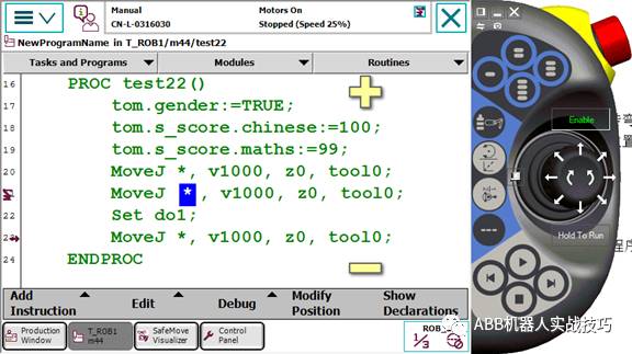
Figure 1 line 21 uses z0
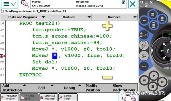
Figure 2 Line 21 uses fine
When the robot is running, the teach pendant has 2 icons, one is the arrow on the left to indicate which line the program has read, and the other is the robot icon, indicating which line the robot is actually taking. In order to achieve smooth transitions, the robot has to read a few lines of code.
If z0 of Figure 1 is used, the robot is on line 21 and the program has been executed to line 23, ie the robot has not yet reached the position and has been opened.
If the fine of Figure 2 is used, the robot is on line 21, and the program is still on line 21, that is, with fine, the program pointer will not be read-ahead, that is, after the robot finishes 21 lines, it will execute open.
ZGAR Foggy Box 7000
ZGAR electronic cigarette uses high-tech R&D, food grade disposable pod device and high-quality raw material. All package designs are Original IP. Our designer team is from Hong Kong. We have very high requirements for product quality, flavors taste and packaging design. The E-liquid is imported, materials are food grade, and assembly plant is medical-grade dust-free workshops.
Our products include disposable e-cigarettes, rechargeable e-cigarettes, rechargreable disposable vape pen, and various of flavors of cigarette cartridges. From 600puffs to 5000puffs, ZGAR bar Disposable offer high-tech R&D, E-cigarette improves battery capacity, We offer various of flavors and support customization. And printing designs can be customized. We have our own professional team and competitive quotations for any OEM or ODM works.
We supply OEM rechargeable disposable vape pen,OEM disposable electronic cigarette,ODM disposable vape pen,ODM disposable electronic cigarette,OEM/ODM vape pen e-cigarette,OEM/ODM atomizer device.


ZGAR FB7000 Vape,ZGAR Foggy Box 7000 disposable electronic cigarette, FB7000 vape pen atomizer , FB7000 E-cig,Foggy Box 7000 disposable electronic cigarette,ZGAR Foggy Box 7000 disposable vape,zgar foggy box
Zgar International (M) SDN BHD , https://www.zgarvapepen.com