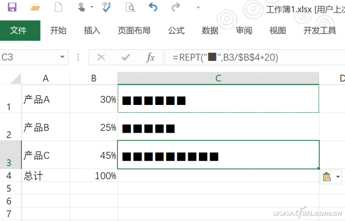
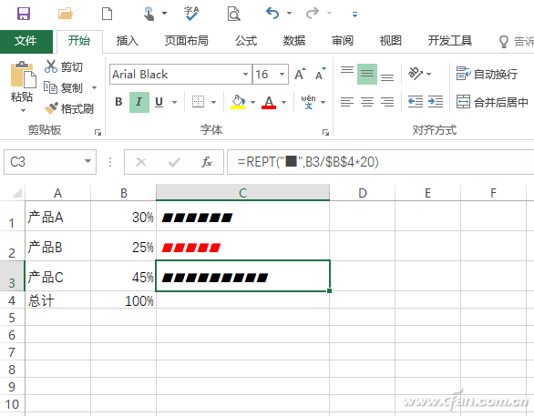
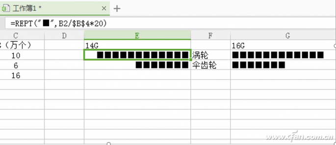
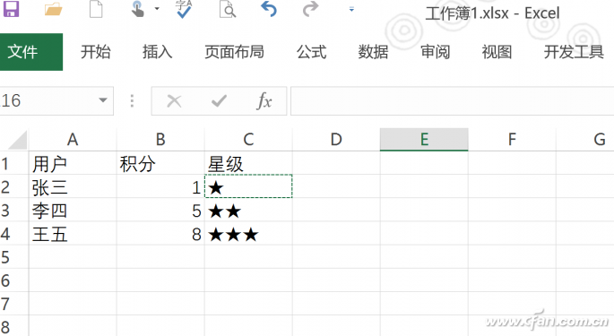
In Excel documents, in order to visualize the data more visually, we often use charts to describe. However, the routine is to use Excel's own chart graphics. This method is cumbersome and inconvenient to personalize. In fact, in addition to charts, we can also use fonts instead of charts to make simpler and more personalized font charts. How to change the font? REPT function analysis Friends who are familiar with Excel functions know that Excel has a function named REPT. Its main function is to repeatedly display texts according to the defined number of times, similar to manually copying texts. In the text, there are many similar "|, â–², â– , ♥" symbols are also a class of fonts, so we can use the REPT function to fill these fonts, in order to achieve replacement of the font fonts, to create more personalized font charts. So in actual use, how can we use the REPT function to character chart? How much data, at a glance In Excel, we often use data bars for labeling in order to visualize how much data is available. Now with the "REPT function + font symbols" can easily achieve the stripe effect. First of all, choose a suitable font symbol. Click "Insert → Symbol → Symbol" in Excel. Select "Normal Text" in the font list of the open symbol, select "Other Symbols" in the subset, and you will see a lot of symbol fonts. Here, you can select “solid square†as the data bar marker. After selecting this character, click “Insert†and insert it into the blank cell for backup (Figure 1). Figure 1 Various graphic fonts in Excel hint: You can see here the "symbol", in fact, a variety of Unicode characters, we can also follow the prompts below the font, enter the corresponding area code, and then press Alt + X to complete the input. For example, type "25a0" and press Alt+X to complete the entity square input. Go to C1 and enter the formula "=REPT("â– ",B1/$B$4*20)" to populate the input formula with a different number of squares (Figure 2). Figure 2 character chart hint: Here is the use of REPT function to fill the square symbol, the symbol can be inserted directly or according to location shortcut key method input, and need to use half-width double quotation marks. B1/$B$4 indicates that the number of input symbols is the ratio of B1 value to B4 (that is, the sum), where $B$4 is used as a relative reference, and adding more products does not affect the reference to the sum. 20 indicates that if the ratio is 1, 20 repeated characters are filled, otherwise the filling is performed according to the proportion. To make the data bar more intuitive, the value here needs to be selected according to the actual situation. If the original data is larger, then the multiple should be set larger. Simple transformation, the chart settings are more casual We all know that using conditional formatting can also be very convenient to add strips to cells, but unlike the above methods, character strips can be very convenient to change the strip size, color, shape, etc., because these changes In fact, only the corresponding changes have been made to the fonts in the cells. For example, in the above example, in order to highlight the smallest number of data, you can change the font in the data bar to red, and adjust the font size and tilt appropriately to complete the change of the data bar (Figure 3). Figure 3 changes to the data bar can be achieved by changing the font Of course, we can also make more changes to the chart by adding more settings to the font. For example, for the two parts of the same model, the above-mentioned function can be used to create a left-right contrast data map. For example, a comparison chart of FIG. 4 needs to be created now, so that the left and right sides of the data can be filled (FIG. 4). Figure 4 need to produce renderings Locate the E2 cell, enter the formula "=REPT("â– ",B2/$B$4*20)", fill it down with its font set to "right-aligned", and enter the formula "=REPT()" in G2 as well. â– ",C2/$C$4*20)", set its font to left-justified (Figure 5). Figure 5 Make a left-right chart Nested Functions to Generate More Personality Charts In addition to transforming fonts, the REPT function can be combined with other functions to generate more useful charts. For example, when rating a customer's consumption level, we often use ★ to indicate the customer's level. If you simply use the above method, the REPT function can only accurately distinguish the customer's star rating when the machine is filled with the ratio. For example, it is necessary to add 1 to 3 star marks according to the customer's consumption points 0→3, 4→7, 8→10, respectively. At this time, integrate the IF function to determine the points, and then use the REPT function to fill in. . Positioning to C2, enter the formula "=IF(B2<=3,REPT("★",1),IF(B2<=7,REPT("★",2),REPT("★",3))) â€, and then fill the formula down, so that the user's points meet the requirements will be in the C column corresponding cells filled with the corresponding asterisk. Press the Enter key to automatically return the specified number of “★†symbols according to the score in the F2 cell (see Figure 6). Figure 6 fills the corresponding star icon hint: Here, three IF decision statements are used to judge the integral of B2. If the score is less than or equal to 3, the corresponding cell is filled with an asterisk. If it is less than or equal to 7, it is filled with 2 asterisks. Otherwise, it is filled with 3 asterisks. In this way, the original REPT fill can be accurately filled according to the actual integration. 0.8mm ( 0.031") Female Header Connector
0.8mm ( 0.031") Female Headers Overview
Through-Hole (Poke-In)
Vertical or Straight Female Header Orientation
One side of the series of pins is connected to PCB board in which the pins can be at a right-angle to the PCB surface (usually called "straight" or [vertical") or.
Single, Dual or Multiple Number of Rows Female Header Connector,0.8Mm Female Pin Header,0.8Mm Female Header,0.8Mm Pcb Header, Pitch 0.8mm Board to Board Connectors ShenZhen Antenk Electronics Co,Ltd , https://www.atkconnectors.com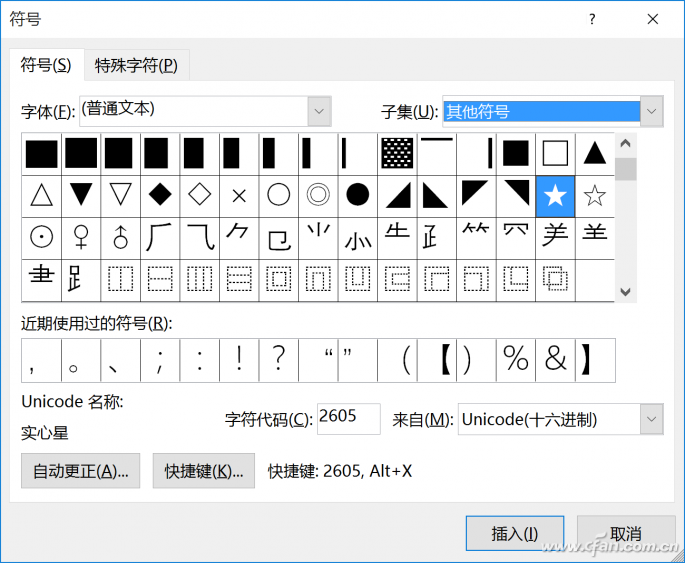

Category:Board To Board Connectors
Sub-Category:Pin Header Female
Type:0.8mm
Whenever there is a need for fitting small-sized connectors in compact devices, the 0.8mm pitch female header, or sometimes referred to as header connector, is ideally suited for this application. Not only does this female header space-savvy, but it is also designed for vacuum pick and place that makes it suitable for high volume automated manufacturing.
Antenk offers these low profile, easy-install, SMT or THM miniature female connector plugs at high quality and affordable China-quoted price, for board-to-board connection, snuggly fitting the pins of a male header and acting as a receptacle.
Assembly and service is simple with either vertical (straight), elevated or at a right angle configuration/orientation, which can dissipate current of about 1.0 A or less in a tape and reel packaging. The filleted corners can also remove shadowing allowing optimization of LED output.
Also, the 0.8mm pitch female headers are made to work in Arduino boards, Arduino Pro and Arduino Mega with either single or double-row female headers, facilitating connections for programming and incorporation into other circuits. They have the perfect height for clearing the USB-B connector and great for stacking multiple shields.
Female header always called as [Header connector", Antenk provide widely range of header connector, from 2.54mm (.100″ inch) pitch to 0.8mm (0.031 inch) pitch. The number of pins (contacts) is from 2 to 40 pins per orw. There are three type: Straight (Dip Vertical), Right angle, SMT (surface mount).
If you can not find the items you interest from above items, welcome to contact us, and you will always get fully responsive from us.
Applications of 0.8mm Pitch Female Headers
Its small size is most suitable for PCB connections of small equipment and devices such as:
Arduino Boards
Architectural and sign lighting
Retail and display lighting
Fluorescent LED retrofit lighting
Cabinet or furniture lighting
Commercial / residential cove lighting
WiFi equipment
Gaming consoles,
Measurement instruments
Medical Diagnostic and Monitoring equipment
Communications: Telecoms and Datacoms
Industrial and Automotive Control and Test
Mount Type: Through-hole vs Surface Mount
At one side of this female header is a series of pins which can either be mounted and soldered directly onto the surface of the PCB (SMT) or placed into drilled holes on the PCB (THM).
Best used for high-reliability products that require stronger connections between layers.
Aerospace and military products are most likely to require this type of mounting as these products experience extreme accelerations, collisions, or high temperatures.
Useful in test and prototyping applications that sometimes require manual adjustments and replacements.
0.8mm vertical single row female header, 0.8mm vertical dual row female header, 0.8mm Elevated single row female header, 0.8mm Elevated dual row female Header, 0.8mm right-angle single row female header and 0.8mm right-angle dual row female header are some examples of Antenk products with through-hole mount type.
Surface-Mount
The most common electronic hardware requirements are SMT.
Essential in PCB design and manufacturing, having improved the quality and performance of PCBs overall.
Cost of processing and handling is reduced.
SMT components can be mounted on both side of the board.
Ability to fit a high number of small components on a PCB has allowed for much denser, higher performing, and smaller PCBs.
0.8mm Right-angle Dual Row female header, 0.8mm SMT Single row female header, 0.8mm SMT Dual row female header and 0.8mm Elevated Dual Row female Header are Antenk`s SMT female headers.
Soldering Temperature for 0.8mm Pitch Female Headers
Soldering SMT female connectors can be done at a maximum peak temperature of 260°C for maximum 60 seconds.
Orientation/Pin-Type: Vertical (Straight) and Right-Angle
0.8mm pitch female headers may be further classified into pin orientation as well, such as vertical or straight male header or right-angle female header.
Right-Angle Female Header Orientation
Parallel to the board's surface (referred to as "right-angle" pins).
Each of these pin-types have different applications that fit with their specific configuration.
PCB Connector Stacking
Profile Above PCB
This type of configuration is the most common way of connecting board-to-board by a connector. First, the stacking height is calculated from one board to another and measured from the printed circuit board face to its highest insulator point above the PCB.
Elevated Sockets/Female Headers
Elevated Sockets aka Stacked sockets/receptacles or Mezzanine are simply stacked female headers providing an exact distance requirement between PCBs that optimizes electrical reliability and performance between PCB boards.
Choosing this type of stacking configuration promotes the following benefits:
Connector Isolation - the contacts are shrouded preventing cable connection mishaps and good guidance for the mating header connectors.
For off-the-shelf wireless PCB module, stacking height is optimized with elevated sockets.
Offers superior strength and rigidity.
Polarisation prevents users from inverted insertion.
For a 1.0mm straight or vertical female header, the standard number of rows that Antenk offers ranges from 1 to 2 rows. However, customization can be available if 3 ,4 or n number of rows is needed by the customer. Also, the number of contacts for the single row is about 2-40 pins while for dual row, the number contacts may vary from 2-80 pins.
Pin Material
The pins of the connector attached to the board have been designed with copper alloy. With customer`s demand the pins can be made gold plated.
Custom 1.0mm Pitch Female Headers
Customizable 1.0 mm pitch female headers are also available, making your manufacturing process way faster as the pins are already inserted in the headers, insulator height is made at the right size and the accurate pin length you require is followed.
Parts are made using semi-automated manufacturing processes that ensure both precision and delicacy in handling the headers before packaging on tape and reel.
Tape and Reel Packaging for SMT Components
Antenk's SMT headers are offered with customizable mating pin lengths, in which each series has multiple number of of circuits, summing up to a thousand individual part number combinations per connector series.
The tape and reel carrier strip ensures that the headers are packaged within accurately sized cavities for its height, width and depth, securing the headers from the environment and maintaining consistent position during transportation.
Antenk also offer a range of custom Tape and reel carrier strip packaging cavities.