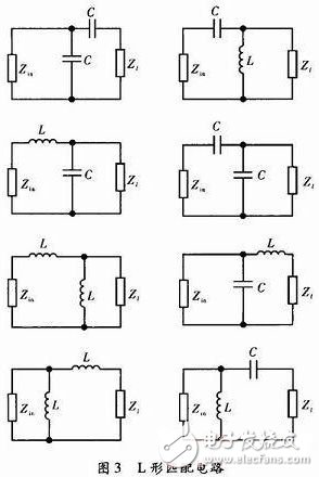
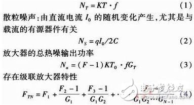
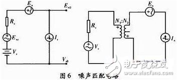
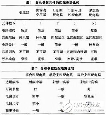
Signals or a wide range of electrical energy During transmission, in order to achieve non-reflective transmission or maximum power transmission of the signal, circuit connections are required to achieve impedance matching. Impedance matching is related to the overall performance of the system, and matching can achieve optimal system performance. The concept of impedance matching is widely used. Impedance matching is common between amplifier circuits at various levels, between amplifier circuits and loads, between signals and transmission circuits, in microwave circuit and system design, whether active or passive. The matching problem must be considered. The root cause is voltage and current in the low-frequency circuit, and the high-frequency mismatch in the guided electromagnetic wave will cause serious reflection and damage to the instrument and equipment. This article describes the principle of impedance matching circuit and its application. Impedance matching is a technical measure to make the microwave circuit or the system reflect and carry the wave as close as possible to the traveling wave state. Impedance matching is divided into two broad categories: (1) The impedance matching between the load and the transmission line makes the load have no reflection. The method is to access the matching device to make the input impedance and the characteristic impedance equal. (2) The matching between the signal source and the transmission line is divided into two cases: 1) The signal source is not reflected, and the method is to connect the signal source to the transmission line to connect the matching device. 2) The signal source is conjugate matched by the method of connecting the matching device between the signal source and the matched circuit. In this case, it is mostly an active circuit design. 2.1 lumped parameter matching circuit Under normal circumstances, the use of capacitive inductance to achieve impedance matching, the use of transformers in the lower frequency band to achieve matching, you can also use L-shaped, π-shaped, T-shaped to achieve matching circuits, such circuits are small in size, simple in structure, and widely used. Transformers: mainly to achieve low frequency bands, with the increase of the working frequency band, the application of such circuits is less and less. The transmission line transformer can realize broadband impedance conversion, and the 4:1 and 1:4 working modes are shown in Figure 1 and Figure 2. Balanced and unbalanced transitions can be achieved, especially in the connection of the TV's external antenna to the coaxial input port. L-shaped matching circuit: This type of circuit has the advantages of simple wiring and low cost, and the disadvantage is narrow-band circuit. Since the matching and power losses are taken into account, inductive and capacitive components are used as much as possible, so there are eight basic circuits to choose from. To design a reasonable matching circuit, we must select the appropriate capacitive reactance component parameters. There are two types of methods for calculating component parameters: direct calculation through impedance and passing through the Smith chart. The former has the advantage of being computationally accurate and suitable for computer calculations. The latter is an intuitive and effective design that can fully and optimally select the optimal performance. It can now be designed directly using a computer and powerful software. T-shaped and 丌-shaped circuits: This kind of circuit can realize the adjustment of the quality factor of the circuit and has higher flexibility. The multi-element matching circuit design can reduce the quality factor of the circuit, but can increase the bandwidth. 2.2 Distributed parameter component circuit matching (1) Hybrid matching circuit (medium and low frequency) This type of circuit design uses as few inductance components as possible because it has high resistance loss and parasitic parameters are also serious. In the design, the parallel connection and transmission line of the capacitor element can be used to complete the design requirements. (2) Single-branch matching circuit Parallel single-branch circuit consists of a series of transmission lines and a parallel open or short-circuit transmission line. The design usually takes the characteristic impedance of a constant transmission line. By adjusting the length of the transmission line, the impedance matching design is performed. (3) Double-branch matching circuit This kind of matching circuit is easier to adjust the matching impedance, but the design is a bit complicated. 2.3 noise matching circuit Thermal noise: Irregular fluctuations in electrons in the resistor will increase with increasing temperature It can be seen that the first level of noise has the greatest impact. When Rs = Rs0, the F = Fmin noise circuit matches. Whether it is a well-designed lumped parameter circuit or a microwave circuit, it is necessary to recognize the characteristics. If the impedance value is to be increased, use the series method. If the impedance value is to be reduced, the parallel mode is used, the two reactances are of the opposite type and resonance is generated. 14 low frequency, mostly using lumped parameter matching circuit, L-shaped matching circuit is the most compact design, but also the low-end preferred. If the quality factor is required in the circuit design, T-shaped or 丌-shaped matching circuits can be used, because the quality factor of such circuits is adjustable, but multi-level matching circuits should also be considered to achieve the frequency response of the circuit. The multi-level matching circuit design is more flexible and can meet the broadband needs of the circuit. The distributed parameter matching circuit is used in the middle and high frequency bands. If it is between the lumped and the distributed, it is better to use a hybrid matching circuit. If the use of a dual-branch circuit does not meet the requirements, a multi-level matching circuit can be considered. The matching design of the circuit is not single. It is necessary to comprehensively consider the interconnection of the bias circuit, the feedback circuit and the frequency adjustment circuit, and it is necessary to repeatedly design and modify, and finally achieve satisfactory results.
The typical distribution box is equipped with a solid case that is capable of protecting the interior components from various adverse conditions, such as excessive exposure to heat or cold. The wiring and other parts that are contained in the box are usually mounted within the interior, helping to lessen the potential for the components to be damaged during any type of shifting that would otherwise create some type of abrasive action on wire coverings and other elements.
The distribution box made of ABS, PC,have good quality and good price.
Waterproof Distribution Box, Outdoor Distribution Box, Distribution Box NINGBO YULIANG TELECOM MUNICATIONS EQUIPMENT CO.,LTD. , https://www.yltelecom.com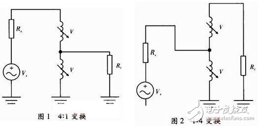

We have a lot of Distribution Point Box,including 1pair drop wire box,4pair STB module box,10pair Distribution Point Box,20pair DP box.What's more,we can provide you 10pair pouyet DP box.
