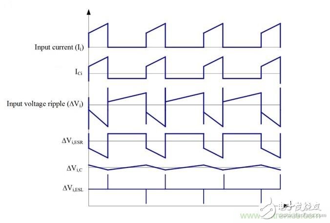
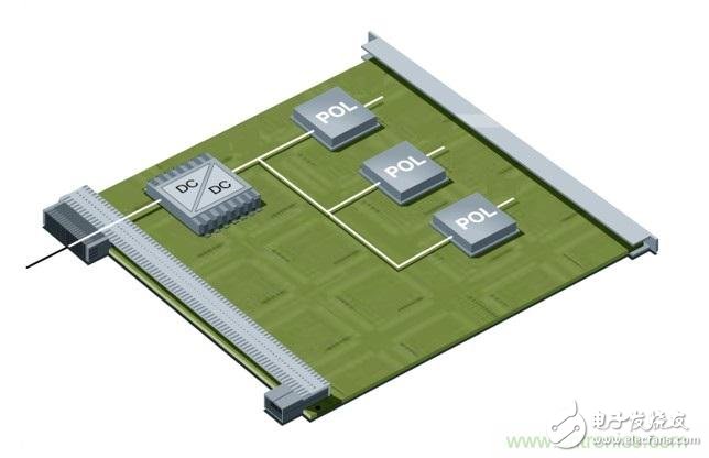
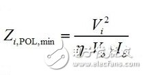
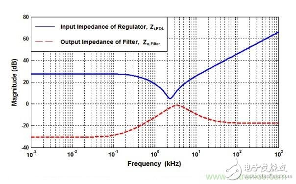
The Ericsson POL regulator is implemented using a non-isolated synchronous buck topology as shown in Figure 1. During normal operation of the buck power stage, QH and QL are alternately switched, and the number of switchings is managed by a control circuit having a fixed frequency PWM scheme. The output current for the buck power stage becomes smooth due to the inductor/capacitor combination at the output. However, since the power switch QH current pulsates from zero to full load during each switching cycle, the input current for the buck power stage is pulsed or chopped. Input capacitors are clearly critical to proper operation of the regulator and to minimize noise emissions from the switching regulator. Figure 1. Simplified schematic and input waveform of a buck converter Many applications use a fairly traditional intermediate bus architecture (IBA), as shown in Figure 2. In IBA, a board-level intermediate bus converter (IBC) feeds multiple POL regulators that are positioned close to the load circuit and provide the final operating voltage. All of these switching converters generate ripple and noise on the common DC input bus and should be suppressed. If there is no filtering, the regulator's input ripple and noise can reach a high enough level to interfere with other devices that use the same power supply. In addition to the input ripple and noise generated by the POL converter, IBC also has its own output voltage ripple and noise. Figure 2 Board-level IBC feeds multiple POL regulators in IBA Therefore, the input filter on the POL regulator can play two important roles. One function is to prevent the electromagnetic interference generated by the switching power supply from reaching the power line and affect other devices. The second function is to protect the converter and its load from the input voltage. Transients that occur in the system, thereby improving system reliability. So what is the source of input ripple and noise in the POL regulator? How do you better design the input filter to mitigate its occurrence? stability A filter with attenuating characteristics sufficient to meet the noise and ripple specifications is added to the input. If the input filter consists only of capacitor (C), stability is not an issue. If the input filter also includes an inductor (LC), it is necessary to check the stability: because the input filter changes the dynamic parameters of the regulator. The output impedance may become larger in certain frequency ranges and may exhibit resonance, which may reduce the sensitivity of the audio. The problem is that the LC input filter can affect the dynamic parameters of the converter and usually degrade the performance of the regulator. An important but often overlooked aspect of input filter design is to meet the Middlebrook specification. According to this specification, if the output impedance curve of the input filter is much lower than the input impedance curve, the input filter will not significantly change the converter loop gain, as shown in Equation 1: In other words, to avoid oscillation, the key is to ensure the peak output impedance of the filter, Zo, which remains below its input impedance, Zi, POL. As shown in Figure 3, the POL regulator is designed to provide a constant voltage to the load, (almost) independent of the load current. Therefore, the minimum input impedance Zi, POL, min of the regulator over the controller bandwidth is calculated as Equation 2: Here: Vi is the input voltage, Vo is the output voltage, Io is the steady-state output load current, and η is the efficiency of the regulator. Figure 3 Example of the output impedance of the input filter and the input impedance of the regulator Input ripple and noise source For POL regulators, the input ripple and noise have three components, the first appearing at the fundamental switching frequency, commonly referred to as ripple. The second component is the AC voltage offset on the input bus due to load transients on the POL module output, which is typically a duration of hundreds of microseconds with tens of kHZ equivalents. The low frequency phenomenon of frequency. Our factory can produce the galvanized traffic signal steel poles with various height. Traffic Signal Steel Pole,Camera Galvanized Lamppost,Traffic Signal Lighting Pole,Hot-Dip Galvanized Traffic Signal Light Pole Jiangsu Baojuhe Science and Technology Co.,Ltd. , https://www.galvanizedsteelpole.com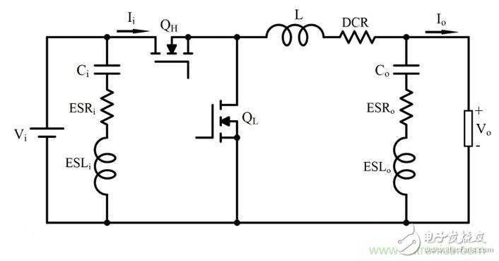

What is the source of input ripple and noise in the POL regulator?
The input filter on the POL regulator can play two important roles. One function is to prevent electromagnetic interference generated by the switching power supply from reaching the power line and affect other devices. The second function is to protect the converter and its load from the input voltage. Transients that increase system reliability. Therefore, the input capacitor is critical to proper operation of the regulator and to minimize noise emissions from the switching regulator.