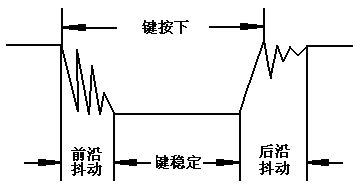
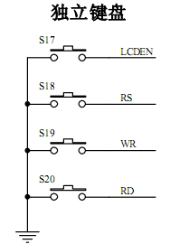
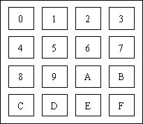
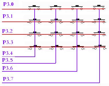
First, basic knowledge 1 key classification and input principle The keys are divided into two categories according to the Structural Principles Division. One is contact-type switch keys, such as mechanical switches, conductive rubber-type switch lights; the other is non-contact switch keys, such as electrical keys, magnetic induction keys, etc. . The former has a low cost, while the latter has a long life. At present, the most common type of computer system is a contact switch button. In the SCM application system, in addition to the reset button has a special reset circuit and a special reset function, the other buttons are to set the control function or input data in the switch state. When the set function key or numeric key is pressed, the computer application system should complete the functions set by the key, and the process of key information input is closely related to the software structure. For a group of keys or a keyboard, there is always one interface circuit connected to the CPU. The CPU can use query or interrupt to know whether the key is input, and check which key is pressed, and send the key number to the accumulator, and then jump to the function program to execute the key, after the execution is completed. Return to the main program. 2. Key structure and features Microcomputer keyboards usually use mechanical contact key switches, and their main function types convert mechanical on-off into electrical logic. That is, it can provide standard TTL logic levels to facilitate logic level compatibility of general purpose digital systems. When the mechanical key is pressed or released, due to the effect of the mechanical elasticity, the mechanical contact is usually accompanied by a certain amount of time, and then the contact is stabilized. The jitter process is shown in Figure 1 below. The jitter time is related to the mechanical characteristics of the switch, typically 5-10ms. Detecting the on and off of the button during the contact jitter may cause an error in the judgment. That is, the button is pressed or released once and the error is considered to be multiple operations. This is not allowed. In order to overcome the misjudgment caused by the mechanical vibration of your key contacts, you must take measures to eliminate jitter. When the number of keys is small, the hardware can be used to eliminate jitter; Figure 1 Mechanical contact of button contacts (1) Key code A group of buttons or keyboards must query the switch state of the button through the I/O line. Depending on the keyboard structure, different encodings are used. Regardless of whether or not there is a code, and what code is used, it is finally converted into a key corresponding to the value in the accumulator to implement the jump of the key function program. (2) Keyboard program A complete keyboard control program should have the following features: a. Check whether the button is pressed, and take the hardware or software measures to shake off. b. There are reliable logic solutions. Each time only one key is processed, the operation of any key during the period has no effect on the system, and no matter how long a key time is, the system executes the key function program only once. c. Accurately output the key value (or key number) to meet the jump instruction requirement. 3 independent keys and matrix keyboard (1) Independent keys In the SCM control system, if only a few function keys are needed, a stand-alone key structure can be used. A single button circuit with independent button type directly formed by I/O lines, its characteristic type, each button occupies a single I/O port line, the work of each button will not affect the state of other I/O lines. The typical application of independent keys is shown in the figure. The independent button circuit configuration is flexible, and the software structure is simple, but each button must occupy one I/O port line. Therefore, when there are many buttons, the I/O port line wastes a lot and should not be used. Independent buttons are shown in Figure 2. Figure 2 independent keyboard Independent button software often uses query structure. Firstly, the input status of the I/O line is not checked on a bit-by-bit basis. If a certain I/O line input is low, you can confirm that the corresponding button on the I/O line has been pressed, and then Turn to the function handler for this key. (2) Matrix Keyboard In the SCM system, if there are many buttons, such as electronic code locks, telephone keyboards, etc., there are generally at least 12 to 16 buttons, and matrix keyboards are generally used. Matrix keyboard, also known as the rank keyboard, uses four I/O lines as the row lines and four I/O lines as the keyboard of the column lines. Set a key at each intersection of the row and column lines. So the number of keys on the keyboard is 4*4. This determinant keyboard structure can effectively improve the utilization of I/O ports in the microcontroller system. How Matrix Keyboard Works The most common keyboard layout is shown in Figure 3. Generally consists of 16 keys, in the MCU can be used to implement a 16-button function with a P port, which is the most common form of microcontroller systems, 4 * 4 matrix keyboard internal circuit shown in Figure 4. Figure 3 matrix keyboard layout Figure 4 matrix keyboard internal circuit diagram When no key is closed, open circuit between P3.0~P3.3 and P3.4~P3.7. When a key is closed, the two I/O lines connected to the closed key are short-circuited. The method for judging whether or not the key is pressed is: in the first step, the column lines P3.4 to P3.7 are input states, and the low level is output from the row lines P3.0 to P3.3, and the column line data is read. When a column line is low, there is a key closure on the column line. In the second step, the row lines output low level in turn, reading data from the column lines P3.4~P3.7. If there is a certain column low, there is a key press on the corresponding row line. Combining the results of steps one or two, the key number can be determined. However, when the key is closed, the key function operation can only be performed once. Therefore, after the key is released, the key function operation is performed. Otherwise, if the key is pressed once, the same key operation may be performed multiple times in succession. There are many ways to identify keys. The most common method is the scanning method. When a key is pressed, the row and column lines connected to this key are turned on, and the row line is at a high level when no key is pressed. If all the column lines are at a high level, whether the key is pressed or not does not cause a change in the line level, so all the column lines must be at a level. In this way, when there is a key press, the row where the key is changed will change from high to low. In order to determine the corresponding line has a key press. A small number of independent keys can be flexibly coded according to actual needs. Matrix keyboard, the position of the key is uniquely determined by the row number and the column number, so the row number and the column number can be binary coded respectively, and then two values ​​are combined into one byte, the high 4 bits are the line numbers, and the low 4 bits are the column numbers. 4. How the keyboard works The response to the keyboard depends on the working mode of the keyboard. The working mode of the keyboard should be determined according to the working condition of the CPU in the actual application system. The principle of selecting the keyboard is to ensure that the CPU can respond to the key operation in time and not occupy too much CPU. Working hours. There are usually three types of keyboard operation, program scanning, timing scanning, and interrupt scanning. (1) Programming scan mode The program scan mode is to use the spare time of the CPU to complete other work and invoke the keyboard scan subroutine to respond to the keyboard input requirements. When the key function program is executed, the CPU does not respond to the key input request until the CPU re-scans the keyboard. (2) Scheduled scan mode The regular scan mode is to scan the keyboard once every time. It uses the internal timer of the microcontroller to generate a certain time (for example, 10ms). When the timer expires, a timer overflow interrupt is generated. The CPU scans the keyboard after responding to the interruption, recognizes the key when the key is pressed, and executes the function program of the key. (3) interrupt scan mode In the above two keyboard scanning methods, whether the key is pressed or not, the CPU must periodically scan the keyboard. When the SCM application system is working, it is not always necessary to input the keyboard. Therefore, the CPU is often in an empty scan state. In order to improve the efficiency of the CPU, interrupt scanning can be used. The working process is as follows: When no key is pressed, the CPU processes its own work. When a key is pressed, an interrupt request is generated. The CPU then executes a keyboard scanning subroutine and recognizes the key number. ESEN Optoelectronics Technology Co., Ltd, , https://www.esenlcd.com


