For industrial control systems with large system, strong real-time performance, many functions, large storage capacity and strong expansion capability, multiple single-chip microcomputers can be used to form a multi-microprocessor system, which has parallel processing functions. The information exchange between the microprocessors working in parallel can be serial communication or parallel communication. However, for systems with strong real-time performance and large amount of information exchange, only the parallel communication method can meet the requirements of system functions. In this section, some practical experiences are introduced, and the multi-chip communication of modular structure is emphasized. 2. 8255A working mode 2 mode control word setting If mode 2 parallel communication interrupt is enabled, PC6 (enable output interrupt) and PC4 (interrupt input enable) can be set, that is, the PCO execution bit operation of the 8255A is set. Optical Line Terminal (OLT)
POE (Power Over Ethernet) refers to the use of IP-based terminals (such as IP phones, wireless LAN access points AP, network cameras) without any changes to the existing Ethernet Cat.5 cabling infrastructure. Etc.) The technology that can provide DC power for such devices while transmitting data signals is a switch that supports Power over Ethernet.
POE is also known as a power supply system based on local area network (POL, Power over LAN) or Active Ethernet (Active Ethernet), sometimes also referred to as Power over Ethernet for short. This is the use of existing standard Ethernet transmission cables to transmit data and data at the same time. The latest standard specification of electric power, and maintains compatibility with existing Ethernet systems and users. The IEEE 802.3af standard is a new standard based on the POE of the Ethernet power supply system. It adds related standards for direct power supply through the network cable on the basis of IEEE 802.3. It is an extension of the existing Ethernet standard and the first international standard for power distribution. standard. Ethernet Poe Switches,Din Rail Mount Switch,Gigabit Din Rail Poe Switch,Managed Port Industrial Switch Shenzhen Scodeno Technology Co.,Ltd , https://www.scodenonet.com
The Intel 8255A is a general-purpose parallel interface circuit that can be programmed to select its logic functions. The chip can be directly interfaced with the 51 series microcontroller. The 8255A has three 8-bit parallel ports: port A, port B, and port C. There are three working modes to choose from: mode 0 is the basic input / output mode; mode 1 is the strobe input / output mode; mode 2 is the bidirectional strobe input / output mode (only for port A).
The parallel communication between the multi-chip processing systems composed of the 51 series single-chip microcomputer 8031 ​​is realized by the working mode 2 of the port 8 of the 8255A.
1. The main function of 8255A working mode 2
1-port A is an 8-bit bidirectional bus port with I/O capability.
Port 2 B is an 8-bit input/output port, and port B0~2 is a 3-bit input/output port that can work in mode O or mode 1.
Port 3 C is a 5-bit control port.
The control port functions are as follows:
â—INTR (PC3) Interrupt request signal line, active high.
â— OBF inverting (PC7) output buffer full/empty status flag line. OBF=O, indicating that the CPU has written data to the port.
The output port data is valid; when the data is taken away by the peripheral, OBF=1.
â— IBF (PCs) input register full / empty status flag line. IBF=1, indicating that the peripheral has hit the data port latch
But the CPU has not yet read; when the CPU reads the port data, IBF=O.
â— ACK inverting (PC6) The peripheral responds to the input signal line. Indicates a peripheral when a negative pulse from a peripheral occurs on the ACK
The port data has been taken away.
â— STB inverting (PC4) peripheral strobe input signal line. Timing on the falling edge of the STB signal, the peripheral will be on the port data line
The information is entered into the port register.
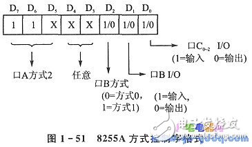
The format of the 8255A mode control word is shown in Figure 1-51. 
IEEE began to develop the standard in 1999, and the earliest participating vendors were 3Com, Intel, PowerDsine, Nortel, Mitel and National Semiconductor. However, the shortcomings of this standard have been restricting the expansion of the market. Until June 2003, the IEEE approved the 802.3af standard, which clearly stipulates the power detection and control items in the remote system, and connects routers, switches, and hubs to IP phones, security systems, and wireless LANs through Ethernet cables. The method of power supply for points and other equipment is regulated. The development of IEEE 802.3af includes the efforts of many company experts, which also allows the standard to be tested in all aspects.
The IEEE 802.3at standard was formulated in 2005 and promulgated in 2009. The 802.3at standard output power can reach 30W, and the available power at the receiving end is 25.5W.
The IEEE 802.3 working group and various manufacturer alliances launched POH-POWER OVER HDBASET in the industry at the end of 2012.
Using the current 4-Pair four-pair wire technology plus, the bilateral power supply can reach 60-100W power, which can be achieved by using 5 or 6 types of wires. It is used in high-definition video promotion to supply power to 42" LED TVs. According to the new regulations in 2010, the power consumption of 42" LED TVs needs to be less than 70W.